INSPECTION
Inspection
| SMR1 AND SYSTEM MAIN RESISTOR |

Measure the resistance between the 3 (CON1) and 4 (GND) terminals of the connector for the relay drive of the HV relay assembly.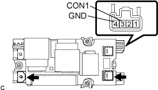

- Standard resistance:
- 70 to 165 Ω (at -30 °C (-22°F) to 80 °C (176°F))
Increase battery voltage between the 3 (CON1) and 4 (GND) terminals of the connector for the relay drive of the HV relay assembly, and measure the resistance between the terminal of the HV battery side positive connector and the w/ convertor inverter assembly side positive terminal of the HV relay assembly.
- HINT:
- The standard resistance indicates the resistance of the system main resistor.
- Standard resistance:
- 28.5 to 31.5 Ω
| SMR2 |
Measure the resistance between the 1 (CON2) and 4 (GND) terminals of the connector for the relay drive of the HV relay assembly.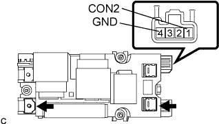
- Standard resistance:
- 20 to 60 Ω (at -35°C (-31°F) to 80°C (176°F))
Increase battery voltage between the 1 (CON2) and 4 (GND) terminals of the connector for the relay drive of the HV relay assembly, and measure the resistance between the terminal of the HV battery side positive connector and the w/ converter inverter assembly side positive terminal of the HV relay assembly.
- Standard resistance:
- Below 1 Ω
| SMR3 |
Measure the resistance between the 2 (CON3) and 4 (GND) terminals of the connector for the relay drive of the HV relay assembly.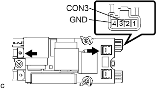
- Standard resistance:
- 20 to 60 Ω (at -35°C (-31°F) to 80°C (176°F))
Increase battery voltage between the 2 (CON3) and 4 (GND) terminals of the connector for the relay drive of the HV relay assembly, and measure the resistance between the terminal of the HV battery side negative connector and the w/ converter inverter assembly side negative terminal of the HV relay assembly.
- Standard resistance:
- Below 1 Ω