INSTALLATION
Removal / installation
| 1. INSTALL BATTERY SMART UNIT |

- NOTICE:
- Wear insulating gloves and protective glasses.
Install the battery smart unit with the 4 bolts.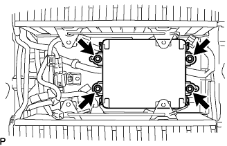

- Torque:
- 7.5 N*m{ 76 kgf*cm , 66 in.*lbf }
Connect the 5 connectors and 2 clamps.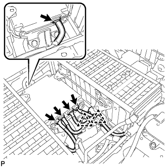
| 2. CHECK HIGH VOLTAGE CABLE CONNECTION |
- CAUTION:
- Wear insulating gloves and protective glasses.
Check that each wire harness is being installed securely.
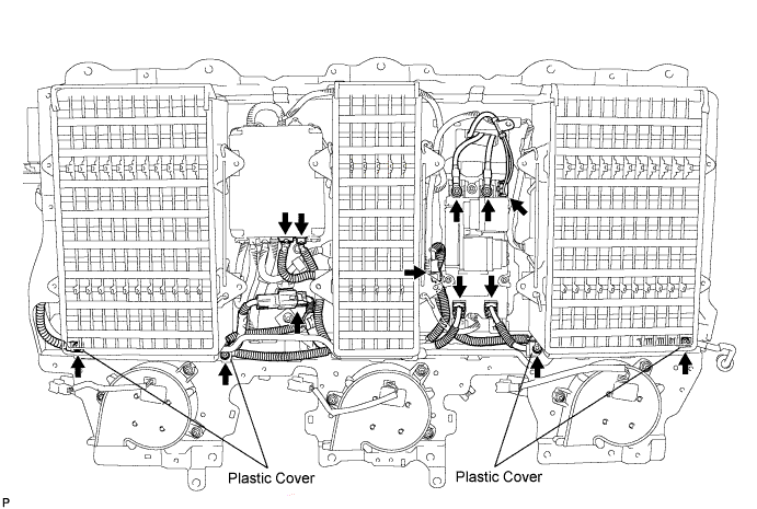
- NOTICE:
- The connectors should be connected securely.
- The nuts should be fastened securely.
- Make sure that the 4 plastic covers are engaged securely.
- The connectors should be connected securely.
| 3. INSTALL BATTERY COVER SUB-ASSEMBLY |
- CAUTION:
- Wear insulating gloves.
Install the battery cover lock striker then push the button to lock.
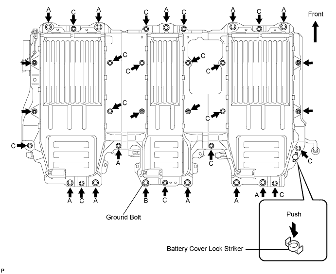
Install the battery cover with the 28 bolts and 6 nuts.
- NOTICE:
- Use a ground bolt for position B.
- Torque:
- Bolt A:
- 25 N*m{ 255 kgf*cm , 19 ft.*lbf }
- Bolt B:
- 25 N*m{ 255 kgf*cm , 19 ft.*lbf }
- Bolt C:
- 7.5 N*m{ 76 kgf*cm , 66 in.*lbf }
- Nut:
- 7.5 N*m{ 76 kgf*cm , 66 in.*lbf }
Connect the No.3 wire frame with the bolt.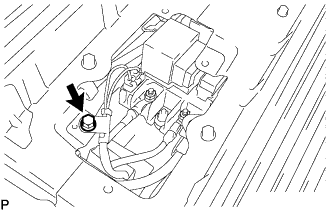
- Torque:
- 8.0 N*m{ 82 kgf*cm , 72 in.*lbf }
| 4. INSTALL HV BATTERY SERVICE HOLE COVER |
Install the battery cover lock striker, then push the button to lock.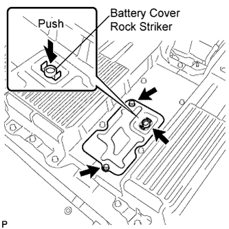
Install the battery service hole cover with the 2 bolts.
- Torque:
- 7.5 N*m{ 76 kgf*cm , 66 in.*lbf }
| 5. INSTALL BATTERY CARRIER DUCT |
Install the battery carrier duct (RH) with the 2 bolts.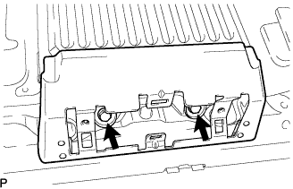
- Torque:
- 7.5 N*m{ 76 kgf*cm , 66 in.*lbf }
Install the battery carrier duct (CTR) with the 2 bolts.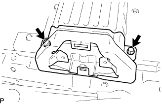
- Torque:
- 7.5 N*m{ 76 kgf*cm , 66 in.*lbf }
Install the battery carrier duct (LH) with the 2 bolts.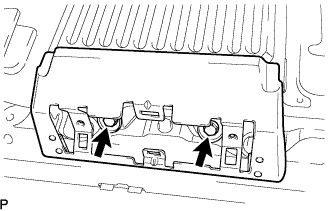
- Torque:
- 7.5 N*m{ 76 kgf*cm , 66 in.*lbf }
| 6. INSTALL BATTERY CARRIER BRACKET |
Install the battery carrier bracket with the 2 bolts.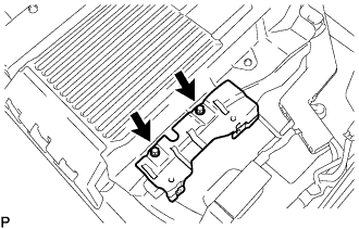
- Torque:
- 7.5 N*m{ 76 kgf*cm , 66 in.*lbf }
| 7. INSTALL REAR CENTER SEAT INNER BELT |
Install the rear center seat inner belt assembly with the bolt.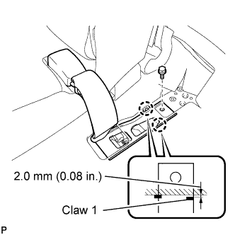
- Torque:
- 42 N*m{ 428 kgf*cm , 31 ft.*lbf }
- NOTICE:
- Tighten the bolt while the claws of the rear center seat inner belt assembly are in contact with the vehicle body.
- Claw 1 shown in the illustration can have a clearance of up to 2.0 mm (0.08 in.) between the claw and the vehicle body.
- Tighten the bolt while the claws of the rear center seat inner belt assembly are in contact with the vehicle body.
- HINT:
- Place the buckle of the rear center seat inner belt assembly on the floor carpet so that the buckle does not interfere with installation of the seat.
| 8. INSTALL FLOOR CARPET ASSEMBLY FRONT |
Install the front floor carpet.
| 9. INSTALL AIR INTAKE COVER CENTER |
Install the air intake cover with the 2 screws.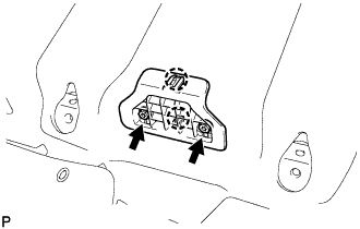
Install the 2 hole covers.
| 10. INSTALL AIR INTAKE COVER |
Install the air intake cover RH.
Install the air intake cover RH with the 2 screws.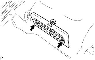
Install the 2 hole covers.
Install the air intake cover LH.
Install the air intake cover LH with the 2 screws.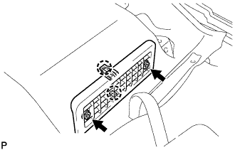
Install the 2 hole covers.
| 11. INSTALL REAR SEAT ASSEMBLY LH |
Place the rear seat assembly LH in the vehicle and align the adjuster pin with the hole on the vehicle side.
Move the rear seat assembly LH to the rearmost position by operating the rear seat track adjusting handle.
- NOTICE:
- Check that the seat is locked.
Temporarily install the front side of the rear seat assembly LH with the 2 bolts.
Recline the separate rear seatback forward by operating the rear seat lock control lever sub-assembly.
Move the rear seat assembly LH fully forward.
- NOTICE:
- Check that the seat is locked.
Temporarily install the rear side of the rear seat assembly LH with the 3 bolts.
Return the separate rear seatback to the upright position.
Move the rear seat assembly LH to the rearmost position by operating the rear seat track adjusting handle.
- NOTICE:
- Check that the seat is locked.
Fully tighten the 2 bolts on the front side of the rear seat assembly LH in the order of the inner side bolt and then the outer side bolt.
- Torque:
- 37 N*m{ 377 kgf*cm , 27 ft.*lbf }
Recline the separate rear seatback forward by operating the rear seat lock control lever sub-assembly.
Move the rear seat assembly LH fully forward.
- NOTICE:
- Check that the seat is locked.
Fully tighten the 3 bolts on the rear side of the rear seat assembly LH in the order of the inner rear side bolt, the inner front side bolt, and then the outer side bolt.
- Torque:
- 37 N*m{ 377 kgf*cm , 27 ft.*lbf }
Return the separate rear seatback to the upright position.
Move the rear seat assembly LH to the rearmost position by operating the rear seat track adjusting handle.
- NOTICE:
- Check that the seat is locked.
Install the floor anchor side of the fold seat stopper band assembly No.2 with the bolt.
- Torque:
- 9.0 N*m{ 92 kgf*cm , 80 in.*lbf }
Install the 3 clips.
| 12. INSTALL REAR SEAT TRACK BRACKET COVER |
| 13. INSTALL REAR SEAT ASSEMBLY RH |
Place the rear seat assembly RH in the vehicle and align the adjuster pin with the hole on the vehicle side.
Move the rear seat assembly RH to the rearmost position by operating the rear seat track adjusting handle.
- NOTICE:
- Check that the seat is locked.
Temporarily install the front side of the rear seat assembly RH with the 2 bolts.
Recline the separate rear seatback forward by operating the rear seat lock control lever sub-assembly.
Move the rear seat assembly RH fully forward.
- NOTICE:
- Check that the seat is locked.
Temporarily install the rear side of the rear seat assembly RH with the 3 bolts.
Return the separate rear seatback to the upright position.
Move the rear seat assembly RH to the rearmost position by operating the rear seat track adjusting handle.
- NOTICE:
- Check that the seat is locked.
Fully tighten the 2 bolts on the front side of the rear seat assembly RH in the order of the inner side bolt and then the outer side bolt.
- Torque:
- 37 N*m{ 377 kgf*cm , 27 ft.*lbf }
Recline the separate rear seatback forward by operating the rear seat lock control lever sub-assembly.
Move the rear seat assembly RH fully forward.
- NOTICE:
- Check that the seat is locked.
Fully tighten the 3 bolts on the rear side of the rear seat assembly RH in the order of the inner rear side bolt, the inner front side bolt, and then the outer side bolt.
- Torque:
- 37 N*m{ 377 kgf*cm , 27 ft.*lbf }
Return the separate rear seatback to the upright position.
Move the rear seat assembly RH to the rearmost position by operating the rear seat track adjusting handle.
- NOTICE:
- Check that the seat is locked.
Install the floor anchor side of the fold seat stopper band assembly No.1 with the bolt.
- Torque:
- 9.0 N*m{ 92 kgf*cm , 80 in.*lbf }
Install the 5 clips.
| 14. INSTALL REAR SEAT TRACK BRACKET COVER |
| 15. INSPECT SLIDE ADJUSTER LOCK SIMULTANEOUSLY |
Check that the left and right adjusters lock simultaneously when sliding the seat.
If the left and right adjusters do not lock simultaneously, adjust by loosening the bolts securing the seat.
| 16. INSTALL SERVICE PLUG GRIP |
- NOTICE:
- Before connecting the service plug, check that no parts and tools remain and that the high voltage terminals and connectors are connected securely.
Wear insulation gloves, then insert the service plug.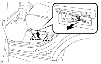
Push down on the grip to lock.
Close the battery service hole cover.
- NOTICE:
- Check that the 2 battery service hole cover clips are securely connected to the battery carrier bracket (click sound).
| 17. CONNECT CABLE TO NEGATIVE BATTERY TERMINAL |
| 18. PERFORM INITIALIZATION |