P0136 During active air-fuel ratio control, following conditions (a) and (b) met for certain period of time (2 trip...
Diagnostic trouble codes
DESCRIPTION
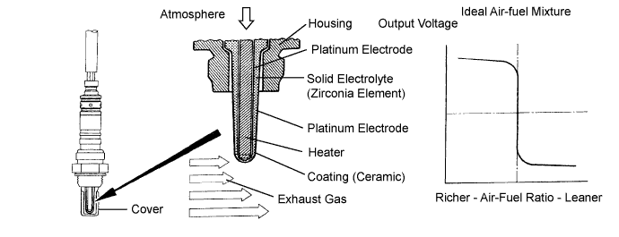
The heated oxygen sensor (HO2S) is used to monitor oxygen in the exhaust gas. For optimum catalyst operation, the air fuel mixture (air-fuel ratio) must be maintained near the ideal "stoichiometric" ratio. The HO2S output voltage changes suddenly in the vicinity of the stoichiometric ratio. The ECM (Included in HV Control ECU) adjusts the fuel injection time so that the air-fuel ratio is nearly stoichiometirc.The HO2S generates a voltage between 0.1 and 0.9 volts in response to oxygen in the exhaust gas. If the oxygen in the exhaust gas increases, the air-fuel ratio becomes "Lean". The ECM interprets Lean when the HO2S voltage is below 0.45 volts. If the oxygen in the exhaust gas decreases, the air-fuel ratio becomes "Rich". The ECM interprets Rich when the HO2S voltage is above 0.45 volts.

| DTC No. |
DTC Detection Condition |
Trouble Area |
| P0136 P0156 |
|
|
| P0137 P0157 |
|
|
| P0138 P0158 |
Out put voltage is more than 0.59 V for 20 seconds or more when air fuel ratio is 14.9 or more. (2 trip detection logic) |
|
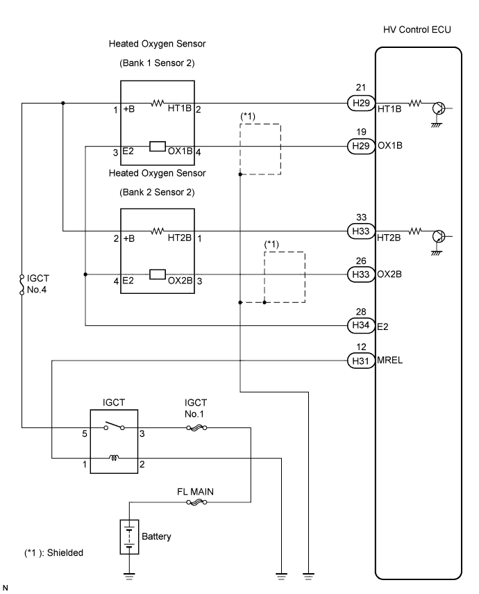
WIRING DIAGRAM
CONFIRMATION DRIVING PATTERN
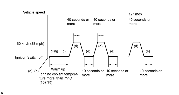
- (a) Connect the intelligent tester to the DLC3.
- (b) Switch the ECM From normal mode to check mode using the tester (Click here).
- (c) Start the engine and warm it up until the engine coolant temperature reaches more than 75°C (167°F).
- (d) Drive the vehicle at 38 mph (60 km/h ) or more for 40 seconds or more.
- (e) Let the engine idle for 10 seconds or more.
- (f) Perform steps (d) and (e) 12 times.
- HINT:
- If a malfunction exists, the MIL illuminates during step (f).
- NOTICE:
- If the conditions in this test are not strictly followed, malfunctions may not be detected. If you do not have the intelligent tester, turn the engine switch off after performing steps from (c) to (f), then perform steps (c) to (f) again.
CONFIRMATION DRIVING PATTERN
Warm up the engine and run the engine at 38 mph (60 km/h) for 7 minutes.CONFIRMATION DRIVING PATTERN
Warm up the engine and run the engine at idle for 30 seconds.INSPECTION PROCEDURE
- HINT:
- Intelligent tester only:
- Malfunctioning ares can be identified by performing the A/F Control function provided in the ACTIVE TEST. The A/F Control function can help to determine whether the Air-Fuel Ratio (A/F) sensor, Heated Oxygen (HO2) sensor and other potential trouble areas are malfunctioning.
- The following instructions describe how to conduct the A/F Control operation using an intelligent tester.
- Connect the intelligent tester to the DLC3.
- Start the engine and turn the tester ON.
- Warm up the engine at engine speed of 2,500 rpm for approximately 90 seconds.
- Put the engine in inspection mode (Click here).
- On the tester, enter the following menus: Powertrain / Engine / Active Test / A/F Control.
- Perform the A/F Control operation with the engine in an idling condition (press the RIGHT or LEFT button to change the fuel injection volume).
- Monitor the voltage outputs of the A/F and HO2 sensors (AFS B1S1 and O2S B1S2 or AFS B2S1 and O2S B2S2) displayed on the tester.
- Connect the intelligent tester to the DLC3.
- HINT:
- The A/F Control operation lowers the fuel injection volume by 12.5 % or increases the injection volume by 25 %.
- Each sensor reacts in accordance with increases in the fuel injection volume.
- The A/F Control operation lowers the fuel injection volume by 12.5 % or increases the injection volume by 25 %.
- Standard:
Tester Display
(Sensor)
Injection Volume
Status
Voltage
AFS B1S1 or AFS B2S1
(A/F)
+25 %
Rich
Less than 3.0
AFS B1S1 or AFS B2S1
(A/F)
-12.5 %
Lean
More than 3.35
O2S B1S2 or O2S B2S2
(HO2)
+25 %
Rich
More than 0.55
O2S B1S2 or O2S B2S2
(HO2)
-12.5 %
Lean
Less than 0.4
- NOTICE:
- The Air-Fuel Ratio (A/F) sensor has an output delay of a few seconds and the Heated Oxygen (HO2) sensor has a maximum output delay of approximately 20 seconds.
| Case |
A/F Sensor (Sensor 1) Output Voltage |
HO2 Sensor (Sensor 2) Output Voltage |
Main Suspected Trouble Area |
||
| 1 |
Injection Volume +25 % -12.5 % |
 |
Injection Volume +25 % -12.5 % |
|
- |
| Output Voltage More than 3.35 V Less than 3.0 V |
 |
Output Voltage More than 0.55 V Less than 0.4 V |
 |
||
| 2 |
Injection Volume +25 % -12.5 % |
|
Injection Volume +25 % -12.5 % |
|
|
| Output Voltage Almost no reaction |
 |
Output Voltage More than 0.55 V Less than 0.4 V |
|
||
| 3 |
Injection Volume +25 % -12.5 % |
|
Injection Volume +25 % -12.5 % |
|
|
| Output Voltage More than 3.35 V Less than 3.0 V |
|
Output Voltage Almost no reaction |
|
||
| 4 |
Injection volume +25 % -12.5 % |
|
Injection Volume +25 % -12.5 % |
|
|
| Output Voltage Almost no reaction |
|
Output Voltage Almost no reaction |
|
||
- HINT:
- If other DTCs relating to different systems that have terminal E2 as the ground terminal are output simultaneously, terminal E2 may have an open circuit.
- Read freeze frame data using the intelligent tester. The ECM records vehicle and driving condition information as freeze frame data the moment a DTC is stored. When troubleshooting, freeze frame data can help determine if the vehicle was running or stopped, if the engine was warmed up or not, if the air-fuel ratio was LEAN or RICH, and other data from the time the malfunction occurred.
- If the OX1B wire from the ECM (Included in HV Control ECU) connector is short-circuited to the +B wire, DTC P0136 will be set.
- If the OX2B wire from the ECM connector is short-circuited to the +B wire, DTC P0156 will be set.
- If other DTCs relating to different systems that have terminal E2 as the ground terminal are output simultaneously, terminal E2 may have an open circuit.
| 1. READ OUTPUT DTC |

Connect the intelligent tester to the DLC3.
Turn the ignition switch ON and turn the tester ON.
Enter the following menus: Powertrain / Engine / DTC.
Read DTCs.
- Result:
Display (DTC Output)
Proceed to
P0138 or P0158
A
P0136 or P0156
B
|
|
||||

| A | |
 |
| 2. READ VALUE USING INTELLIGENT TESTER (OUTPUT VOLTAGE OF HEATED OXYGEN SENSOR) |
Connect the intelligent tester to the DLC3.
Put the engine in inspection mode (Click here).
Start the engine.
Turn the tester ON.
Enter the following menus: Powertrain / Engine / Data List / O2S B1S2 or O2S B2S2.
Allow the engine to idle.
Read the Heated Oxygen (HO2) sensor output voltage while idling.
- Result:
HO2 Sensor Output Voltage
Proceed to
More than 1.2 V
A
Less than 1.0 V
B
|
|
||||
| A | |
|
| 3. CHECK HARNESS AND CONNECTOR (CHECK FOR SHORT) |
Turn the engine switch off and wait for 5 minutes.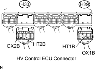
Disconnect the H29 and H33 HV Control ECU connector.
Measure the resistance between the terminals of the HV Control ECU.
- Standard Resistance:
Tester Connection
Specified Condition
HT1B (H29-21) - OX1B (H29-19)
10 kΩ or higher
HT2B (H33-33) - OX2B (H33-26)
10 kΩ or higher
Reconnect the ECM connector.
|
|
||||
| OK | ||
 |
||
| ||
| 4. INSPECT HEATED OXYGEN SENSOR (CHECK FOR SHORT) |
Disconnect the H11 or H20 HO2 sensor connector.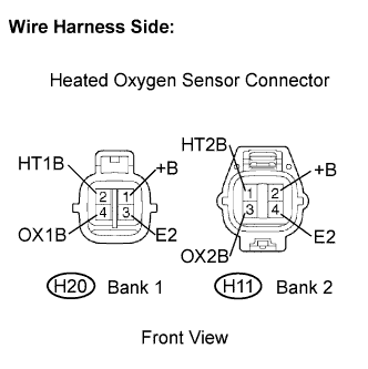
Measure the resistance of the HO2 sensor.
- Standard resistance (Bank 1 sensor 2):
Tester Connection
Specified Condition
+B (H20-2) - E (H20-4)
10 kΩ or higher
+B (H20-2) -OX1B (H20-3)
10 kΩ or higher
- Standard resistance (Bank 2 sensor 2):
Tester Connection
Specified Condition
+B (H11-2) - E2 (H11-4)
10 kΩ or higher
+B (H11-2) -OX2B (H11-3)
10 kΩ or higher
|
|
||||

| OK | |
|
| 5. PERFORM CONFIRMATION DRIVING PATTERN |
| NEXT | |
|
| 6. CHECK WHETHER DTC OUTPUT RECURS (DTC P0138 or P0158) |
On the intelligent tester, enter the following menus: Powertrain / Engine / DTC.
Read DTCS.
- Result:
Display (DTC Output)
Proceed to
P0138 or P0158
A
No output
B
|
|
||||
| A | ||
|
||
| ||
| 7. READ VALUE USING INTELLIGENT TESTER (OUTPUT VOLTAGE OF HEATED OXYGEN SENSOR) |
Connect the intelligent tester to the DLC3.
Put the engine in inspection mode (Click here).
Start the engine.
Turn the tester ON.
Enter the following menus: Powertrain / Engine / Data List / O2S B1S2 or O2S B1S2.
After warming up the engine, run the engine at an engine speed of 2,500 rpm for 3 minutes.
Read the output voltage of the HO2 sensor when the engine rpm is suddenly increased.
- Standard voltage:
- Fluctuates between 0.4 V or less and 0.5 V or more.
|
|
||||
| OK | |
|
| 8. PERFORM CONFIRMATION DRIVING PATTERN |
| NEXT | |
|
| 9. CHECK WHETHER DTC OUTPUT RECURS (DTC P0136 or P0156) |
On the intelligent tester, enter the following menus: Powertrain / Engine / DTC.
Read DTCs.
- Result:
Display (DTC Output)
Proceed to
P0136 or P0156
A
No output
B
|
|
||||
| A | |
|
| 10. REPLACE HEATED OXYGEN SENSOR |
| NEXT | |
|
| 11. PERFORM CONFIRMATION DRIVING PATTERN |
| NEXT | |
|
| 12. CHECK WHETHER DTC OUTPUT RECURS (DTC P0136 or P0156) |
On the intelligent tester, enter the following menus: Powertrain / Engine/ DTC.
Read DTCs.
- Result:
Display (DTC Output)
Proceed to
P0136 or P0156
A
No output
B
|
|
||||
| A | |
|
| 13. PERFORM ACTIVE TEST USING INTELLIGENT TESTER (INJECTION VOLUME) |
Connect the intelligent tester to the DLC3.
Put the engine in inspection mode (Click here).
Start the engine.
Turn the tester ON.
Warm up the engine.
Enter the following menus: Powertrain / Engine / Active Test / Control the Injection Volume.
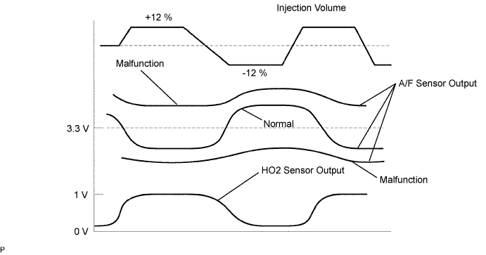
Change the fuel injection volume using the tester, monitoring the output voltage of Air-Fuel Ratio (A/F) and HO2 sensor displayed on the tester.
- HINT:
- Change the fuel injection volume within the range of -12 % and +12 %. The injection volume can be changed in 1 % graduations within the range.
- The A/F sensor is displayed as AFS B1S1 or AFS B2S1, and the HO2 sensor is displayed as O2S B1S2 or O2S B2S2, on the intelligent testers.
- Change the fuel injection volume within the range of -12 % and +12 %. The injection volume can be changed in 1 % graduations within the range.
- Result:
Tester Display (Sensor)
Voltage Variation
Proceed to
AFS B1S1 (A/F)
AFS B2S1 (A/F)
Alternates between more and less than 3.3 V
OK
AFS B1S1 (A/F)
AFS B2S1 (A/F)
Remains at more than 3.3 V
NG
AFS B1S1 (A/F)
AFS B2S1 (A/F)- HINT:
- A normal HO2 sensor voltage (O2S B1S2 or O2S B2S2) reacts in accordance with increases and decreases in fuel injection volumes. When the A/F sensor voltage remains at either less or more than 3.3 V despite the HO2 sensor indicating a normal reaction, the A/F sensor is malfunctioning.
Remains at less than 3.3 V
NG
|
|
||||
| OK | ||
|
||
| ||
| 14. CHECK EXHAUST GAS LEAKAGE |
- OK:
- No gas leakage.
|
|
||||
| OK | |
|
| 15. INSPECT HEATED OXYGEN SENSOR |
Disconnect the H11 or H20 HO2 sensor connector.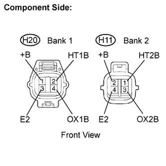
Measure the resistance of the HO2 sensor.
- Standard resistance (Bank 1 sensor 2):
Tester Connection
Specified Condition
+B (H20-2) - E (H20-4)
10 kΩ or higher
+B (H20-2) - OX1B (H20-3)
10 kΩ or higher
- Standard resistance (Bank 2 sensor 2):
Tester Connection
Specified Condition
+B (H11-2) - E2 (H11-4)
10 kΩ or higher
+B (H11-2) - OX2B (H11-3)
10 kΩ or higher
|
|
||||
| OK | |
|
| 16. INSPECT INTEGRATION RELAY (IGCT RELAY) |
Remove the integration relay from the engine room R/B.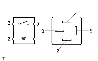
Measure the IGCT relay resistance.
- Standard resistance:
Terminal Connection
Specified Condition
3 - 5
10 kΩ or higher
3 - 5
Below 1 Ω
(When battery voltage applied to terminals 1 and 2)
Reinstall the IGCT relay.
|
|
||||
| OK | |
|
| 17. CHECK HARNESS AND CONNECTOR (HEATED OXYGEN SENSOR - ECM) |
Disconnect the H11 or H20 HO2 sensor connector.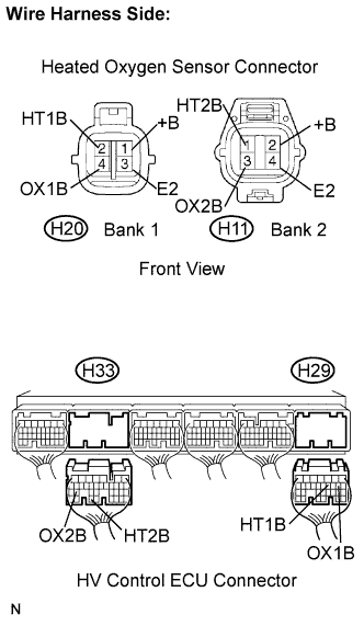
Turn the ignition switch ON.
Measure the voltage between the +B terminal of the HO2 sensor connector and body ground.
- Standard voltage:
Terminal Connection
Specified Condition
+B (H20-2) - Body ground
9 to 14 V
+B (H11-2) - Body ground
9 to 14 V
Turn the engine switch off.
Disconnect the H29, H32 and H33 HV Control ECU connector.
Measure the resistance between terminals of the HO2 sensor and HV Control ECU.
- Standard resistance (Check for open):
Terminal Connection
Specified Condition
HT1B (H20-1) - HT1B (H29-21)
Below 1 Ω
OX1B (H20-3) - OX1B (H29-19)
Below 1 Ω
E2 (H20-4) - E2 (H32-28)
Below 1 Ω
HT2B (H11-1) - HT2B (H33-33)
Below 1 Ω
OX2B (H11-3) - OX2B (H33-26)
Below 1 Ω
E2 (H11-4) - E2 (H32-28)
Below 1 Ω
- Standard resistance (Check for short):
Terminal Connection
Specified Condition
HT1B (H20-1) - HT1B (H29-21) - Body ground
10 kΩ or higher
OX1B (H20-3) - OX1B (H29-19) - Body ground
10 kΩ or higher
E2 (H20-4) - E2 (H32-28) - Body ground
10 kΩ or higher
HT2B (H11-1) - HT2B (H33-33) - Body ground
10 kΩ or higher
OX2B (H11-3) - OX2B (H33-26) - Body ground
10 kΩ or higher
E2 (H11-4) - E2 (H32-28) - Body ground
10 kΩ or higher
Reconnect the HO2 sensor connector.
Reconnect the HV Control ECU connector.
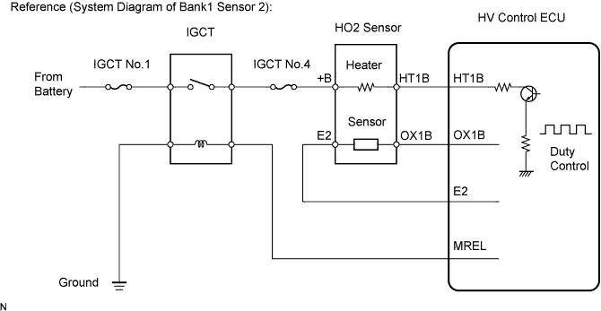
|
|
||||
| OK | ||
|
||
| ||