TERMINALS OF ECU
System information
| CHECK MULTIPLEX NETWORK GATEWAY ECU |
Disconnect the G1 ECU connector.
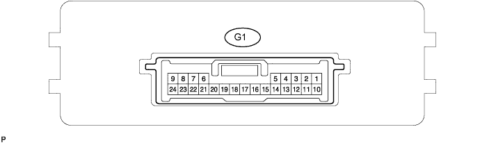

Measure the voltage and resistance of the wire harness side connector.
If the result is not as specified, there may be a malfunction on the wire harness side.Symbols (Terminal No.)
Wiring Color
Terminal Description
Condition
Specified Condition
BATT (G1-10) - GND (G1 24)
SB - W-B
+B (BATT) power supply
Always
10 to 14 V
IG (G1-1) - Body ground
Y - Body ground
Ignition power supply
Ignition switch ON
10 to 14 V
ACC (G1-2) - Body ground
L - Body ground
ACC power supply
Ignition switch ON
10 to 14 V
SIL (G1-7) - Body ground
GR - Body ground
Bus ''+'' line
During transmission
Pulse generation
MPI1 (G1-4) - Body ground
GR - Body ground
MPX line
Always
10 kΩ or higher
MPI2 (G1-13) - Body ground
O - Body ground
MPX line
Always
10 kΩ or higher
MPD1 (G1-3) - Body ground
R - Body ground
MPX line
Always
10 kΩ or higher
MPD2 (G1-12) - Body ground
R - Body ground
W-B - Body ground
Always
10 kΩ or higher
GND (G1-24) - Body ground
W-B - Body ground
Ground
Always
Below 1 Ω
GTX- (G1-21) - Body ground
B - Body ground
AVC-LAN line
Always
10 kΩ or higher
GTX+ (G1-6) - Body ground
R - Body ground
AVC-LAN line
Always
10 kΩ or higher
| CHECK INSTRUMENT PANEL JUNCTION BLOCK (MULTIPLEX NETWORK BODY ECU) |
Disconnect the 1E, 1D and 1F junction block connectors.
Disconnect the B7 ECU connector.
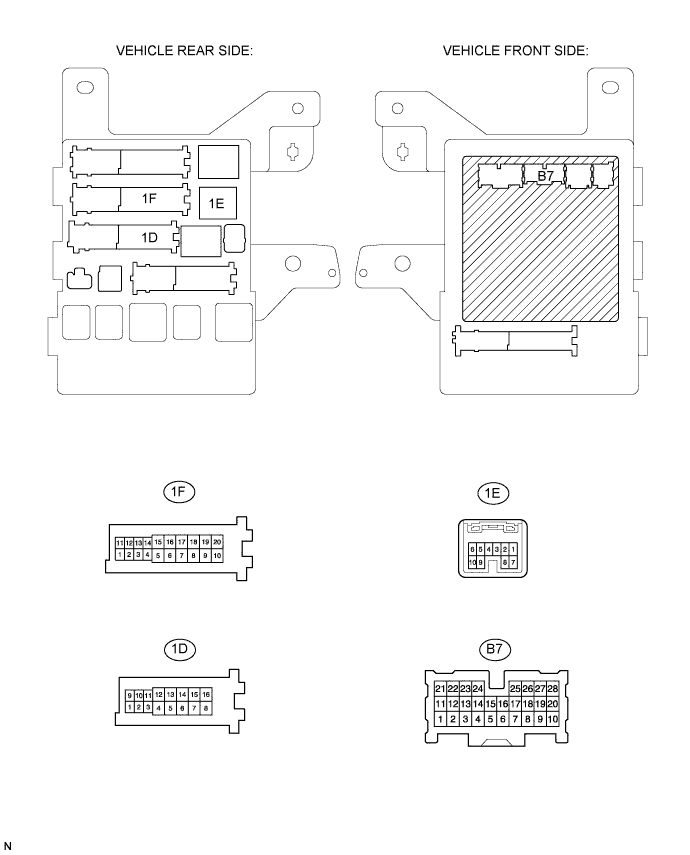
Measure the resistance and voltage of the wire harness side connectors.
If the result is not as specified, there may be a malfunction on the wire harness side.Symbols (Terminals No.)
Wiring Color
Terminal Description
Condition
Specified Condition
BECU (1D-10) - Body ground
SB - Body ground
+B (BECU) power supply
Always
10 to 14 V
MPX1 (1E-7) - Body ground
BR - Body ground
MPX line
Always
10 kΩ or higher
MPX2 (B7-21) - Body ground
O - Body ground
MPX line
Always
10 kΩ or higher
GND1 (1F-10) - Body ground
W-B - Body ground
Ground
Always
Below 1 Ω
| CHECK CENTER CLUSTER INTEGRATION PANEL (W/O LEXUS NAVIGATION SYSTEM) |
Disconnect the C4 panel connector.

Measure the voltage and resistance of the wire harness side connector.
If the result is not as specified, there may be a malfunction on the wire harness side.Symbols (Terminals No.)
Wiring Color
Terminal Description
Condition
Specified Condition
IG+ (C4-9) - Body ground
LG - Body ground
Ignition switch (on) signal
Ignition switch ON
10 to 14 V
MPX+ (C4-5) - Body ground
L - Body ground
MPX line
Always
10 kΩ or higher
MPX- (C4-12) - Body ground
R - Body ground
MPX line
Always
10 kΩ or higher
GND (C4-7) - Body ground
W-B - Body ground
Ground
Always
Below 1 Ω
| CHECK AUTO WIPER ECU |
Disconnect the A31 and A30 ECU connectors.
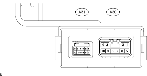
Measure the voltage and resistance of the wire harness side connector.
If the result is not as specified, there may be a malfunction on the wire harness side.Symbols (Terminals No.)
Wiring Color
Terminal Description
Condition
Specified Condition
WIG (A30-10) - Body ground
Y - Body ground
Ignition switch (on) signal
Ignition switch ON
10 to 14 V
MPX1 (A31-1) - Body ground
BR - Body ground
MPX line
Always
10 kΩ or higher
E (A31-12) - Body ground
W-B - Body ground
Ground
Always
Below 1 Ω
| CHECK AFS ECU (W/ ADAPTIVE FRONT-LIGHT SYSTEM) |
Disconnect the A17 ECU connector.
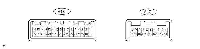
Measure the voltage and the resistance of the wire harness side connector.
If the result is not as specified, there may be a malfunction on the wire harness side.Symbols (Terminals No.)
Wiring Color
Terminal Description
Condition
Specified Condition
IG (A17-2) - Body ground
P - Body ground
Ignition switch (on) signal
Ignition switch ON
10 to 14 V
IGS (A17-12) - Body ground
P - Body ground
Ignition switch (on) signal
Ignition switch ON
10 to 14 V
MPX1 (A17-5) - Body ground
P - Body ground
MPX line
Always
10 kΩ or higher
E1 (A17-1) - Body ground
W-B - Body ground
Ground
Always
Below 1 Ω
| CHECK POSITION CONTROL ECU AND SWITCH ASSEMBLY (W/ DRIVING POSITION MEMORY) |
Disconnect the P30 and P31 ECU connectors.
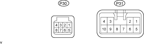
Measure the voltage and the resistance of the wire harness side connector.
If the result is not as specified, there may be a malfunction on the wire harness side.Symbols (Terminals No.)
Wiring Color
Terminal Description
Condition
Specified Condition
+B (P31-5) - Body ground
LG - Body ground
+B (+B) power supply
Always
10 to 14 V
MPX1 (P30-1) - Body ground
W - Body ground
MPX line
Always
10 kΩ or higher
GND (P31-1) - Body ground
W-B - Body ground
Ground
Always
Below 1 Ω
| CHECK AIR CONDITIONING AMPLIFIER (A/C ECU) |
Disconnect the A11 amplifier connector.
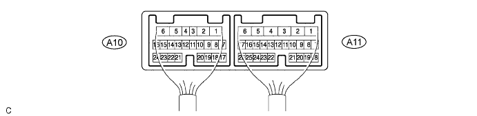
Measure the voltage and resistance of the wire harness side connector.
If the result is not as specified, there may be a malfunction on the wire harness side.Symbols (Terminals No.)
Wiring Color
Terminal Description
Condition
Specified Condition
IG+ (A11-1) - Body ground
Y - Body ground
Ignition switch (on) signal
Ignition switch ON
10 to 14 V
MPX+ (A11-3) - Body ground
BR - Body ground
MPX line
Always
10 kΩ or higher
MPX- (A11-4) - Body ground
GR - Body ground
MPX line
Always
10 kΩ or higher
GND (A11-6) - Body ground
W-B - Body ground
Ground
Always
Below 1 Ω
| CHECK CENTER AIRBAG SENSOR ASSEMBLY |
Disconnect the A24 sensor connector.
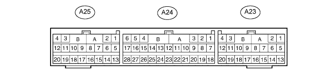
Measure the voltage and resistance of the wire harness side connector.
If the result is not as specified, there may be a malfunction on the wire harness side.Symbols (Terminals No.)
Wiring Color
Terminal Description
Condition
Specified Condition
IG2 (A24-5) - Body grond
B - Body grond
Ignition switch (on) signal
Ignition switch ON
10 to 14 V
MPX1 (A24-24) - Body ground
BR - Body ground
MPX line
Always
10 kΩ or higher
MPX2 (A24-22) - Body ground
BR - Body ground
MPX line
Always
10 kΩ or higher
E2 (A24-28) - Body ground
W-B - Body ground
Ground
Always
Below 1 Ω
| CHECK COMBINATION METER ASSEMBLY (METER ECU) |
Disconnect the C8 and C9 meter connectors.

Measure the voltage and resistance of the wire harness side connector.
If the result is not as specified, there may be a malfunction on the wire harness side.Symbols (Terminals No.)
Wiring Color
Terminal Description
Condition
Specified Condition
B (C8-15) - Body ground
SB - Body ground
+B (B) power supply
Always
10 to 14 V
B (C8-16) - Body ground
O - Body ground
+B (B) power supply
Always
10 to 14 V
MPX+ (C9-4) - Body ground
V - Body ground
MPX line
Always
10 kΩ or higher
MPX- (C8-5) - Body ground
Y - Body ground
MPX line
Always
10 kΩ or higher
E (C9-1) - Body ground
W-B - Body ground
Ground
Always
Below 1 Ω
| CHECK SLIDING ROOF DRIVE GEAR (SLIDING ROOF CONTROL ECU) |
Disconnect the M5 driver gear connector.
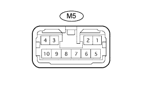
Measure the voltage and the resistance of the wire harness side connector.
If the result is not as specified, there may be a malfunction on the wire harness side.Symbols (Terminals No.)
Wiring Color
Terminal Description
Condition
Specified Condition
B (M5-1) - Body ground
P - Body ground
+B (B) power supply
Always
10 to 14 V
MPX1 (M5-10) - Body ground
R - Body ground
MPX line
Always
10 kΩ or higher
E (M5-7) - Body ground
W-B - Body ground
Ground
Always
Below 1 Ω
| CHECK MULTIPLEX TILT AND TELESCOPIC ECU (W/ DRIVING POSITION MEMORY) |
Disconnect the T4 ECU connector.

Measure the voltage and resistance of the wire harness side connector.
If the result is not as specified, there may be a malfunction on the wire harness side.Symbols (Terminals No.)
Wiring Color
Terminal Description
Condition
Specified Condition
+B (T4-2) - Body ground
Y - Body ground
+B (+B) power supply
Always
10 to 14 V
MPX1 (T4-5) - Body ground
GR - Body ground
MPX line
Always
10 kΩ or higher
MPX2 (T4-14) - Body ground
O - Body ground
MPX line
Always
10 kΩ or higher
GND (T4-11) - Body ground
W-B - Body ground
Ground
Always
Below 1 Ω
| CHECK RAIN SENSOR (W/ AUTOMATIC WIPER SYSTEM) |
Disconnect the R7 sensor connector.

Measure the voltage and resistance of the wire harness side connector.
Symbols (Terminals No.)
Wiring Color
Terminal Description
Condition
Specified Condition
SIG (R7-1) - Body ground
P - Body ground (*1)
B - Body ground (*2)
Ignition switch (on) signal
Ignition switch ON
10 to 14 V
MPX (R7-2) - Body ground
V - Body ground
MPX line
Always
10 kΩ or higher
ES (R7-3) - Body ground
W-B - Body ground
Ground
Always
Below 1 Ω
- *1: w/ Sliding roof system
- *2: w/o Sliding roof system
- *1: w/ Sliding roof system
| CHECK MULTIPLEX NETWORK MASTER SWITCH |
Disconnect the P19 switch connector.
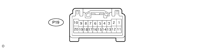
Measure the voltage and resistance of the wire harness side connector.
If the result is not as specified, there may be a malfunction on the wire harness side.Symbols (Terminals No.)
Wiring Color
Terminal Description
Condition
Specified Condition
CPUB (P19-9) - Body ground
L-B - Body ground
+B (CPUB) power supply
Always
10 to 14 V
GND (P19-2) - Body ground
W-B - Body ground
Ground
Always
Below 1 Ω
MPX1 (P19-7) - Body ground
R - Body ground
MPX line
Always
10 kΩ or higher
MPX2 (P19-8) - Body ground
GR - Body ground
MPX line
Always
10 kΩ or higher
| CHECK MULTIPLEX BACK DOOR ECU |
Disconnect the P10 and P11 ECU connectors.
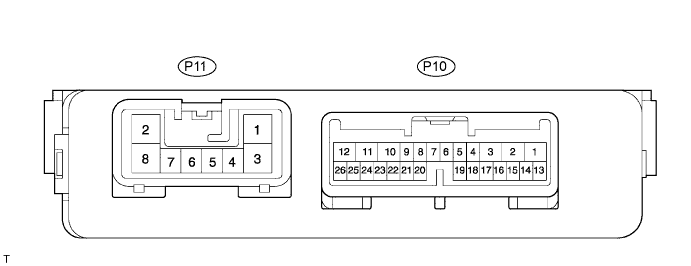
Measure the voltage and resistance of the wire harness side connector.
If the result is not as specified, there may be a malfunction on the wire harness side.Symbols (Terminals No.)
Wiring Color
Terminal Description
Condition
Specified Condition
B (P11-2) - Body ground
Y - Body ground
+B (B) power supply
Always
10 to 14 V
MPX1 (P10-22) - Body ground
SB - Body ground
MPX line
Always
10 kΩ or higher
GND (P11-8) - Body ground
W-B - Body ground
Ground
Always
Below 1 Ω
| CHECK TRANSPONDER KEY ECU |
Disconnect the T8 ECU connector.

Measure the resistance and voltage of the wire harness side connector.
If the result is not as specified, there may be a malfunction on the wire harness side.Symbols (Terminals No.)
Wiring Color
Terminal Description
Condition
Specified Condition
CPUB (T8-1) - Body ground
V - Body ground
B (CPUB) power supply
Always
10 to 14 V
MPX1 (T8-4) - Body ground
O - Body ground
MPX line
Always
10 kΩ or higher
MPX2 (T8-5) - Body ground
R - Body ground
MPX line
Always
10 kΩ or higher
GND (T8-14) - Body ground
W-B - Body ground
Ground
Always
Below 1 Ω
| CHECK OUTER MIRROR CONTROL ECU LH (W/ DRIVING POSITION MEMORY) |
Disconnect the R17 ECU connector.
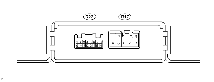
Measure the resistance and voltage of the wire harness side connector.
If the result is not as specified, there may be a malfunction on the wire harness side.Symbols (Terminals No.)
Wiring Color
Terminal Description
Condition
Specified Condition
CPUB (R17-7) - Body ground
L-B - Body ground
B (CPUB) power supply
Always
10 to 14 V
MPX1 (R17-6) - Body ground
R - Body ground
MPX line
Always
10 kΩ or higher
GND (R17-1 ) - Body ground
W-B - Body ground
Ground
Always
Below 1 Ω
| CHECK OUTER MIRROR CONTROL ECU RH |
Disconnect the R18 ECU connector.
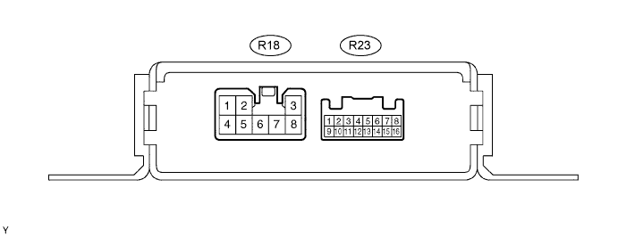
Measure the resistance and voltage of the wire harness side connector.
If the result is not as specified, there may be a malfunction on the wire harness side.Symbols (Terminals No.)
Wiring Color
Terminal Description
Condition
Specified Condition
CPUB (R18-7) - Body ground
L-B - Body ground
B (CPUB) power supply
Always
10 to 14 V
MPX1 (R18-6) - Body ground
L - Body ground
MPX line
Always
10 kΩ or higher
GND (R18-1 ) - Body ground
W-B - Body ground
Ground
Always
Below 1 Ω
| CHECK DOUBLE DOOR LOCK ECU |
Disconnect the D2 ECU connector.

Measure the resistance and voltage of the wire harness side connector.
If the result is not as specified, there may be a malfunction on the wire harness side.Symbols (Terminals No.)
Wiring Color
Terminal Description
Condition
Specified Condition
+B (D2-1) - Body ground
R - Body ground
B (+B) power supply
Always
10 to 14 V
MPX1 (D2-9) - Body ground
LG - Body ground
MPX line
Always
10 kΩ or higher
GND (D2-14) - Body ground
W-B - Body ground
Ground
Always
Below 1 Ω