Power Steering ECU Communication Stop Mode
Circuit diagnosis
DESCRIPTION
| Detection Item |
Symptom |
Suspected Area |
| POWER STEERING ECU COMMUNICATION STOP MODE |
|
|
WIRING DIAGRAM
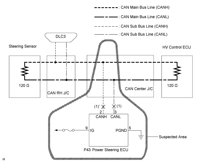

INSPECTION PROCEDURE
| 1. CHECK CAN BUS LINE FOR DISCONNECTION (POWER STEERING ECU SUB BUS LINE) |

Turn the ignition switch off.
Disconnect the power steering ECU connector (P43).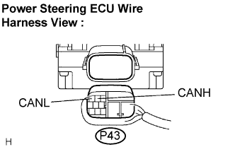
Measure the resistance according to the value(s) in the table below.
- Standard Resistance:
Tester Connection
Condition
Specified Value
P43-2 (CANH) - P43-3 (CANL)
Disconnect the negative auxiliary battery cable
54 to 69 Ω
|
|
||||

| OK | |
 |
| 2. CHECK WIRE HARNESS (IG, PGND) |
Measure the resistance according to the value(s) in the table below.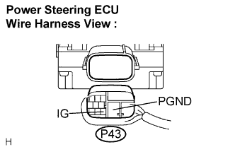
- Standard Resistance:
Tester Connection
Condition
Specified Value
P43-5 (PGND) - Body ground
Always
Below 1 Ω
Measure the voltage according to the value(s) in the table below.
- Standard Voltage:
Tester Connection
Condition
Specified Value
P43-9 (IG) - Body ground
Ignition switch on
10 to 14 V
|
|
||||
| OK | ||
 |
||
| ||