Short to GND in CAN Bus Line
Circuit diagnosis
DESCRIPTION
There may be a short circuit between the CAN bus line and GND when the resistance between terminals 6 (CANH) and 4 (CG), or terminals 14 (CANL) and 4 (CG) of the DLC3 is below 1 KΩ.| Symptoms |
Suspected Area |
| Resistance between terminals 6 (CANH) and 4 (CG), or terminals 14 (CANL) and 4 (CG) of the DLC3 is below 1 kΩ. |
|
WIRING DIAGRAM
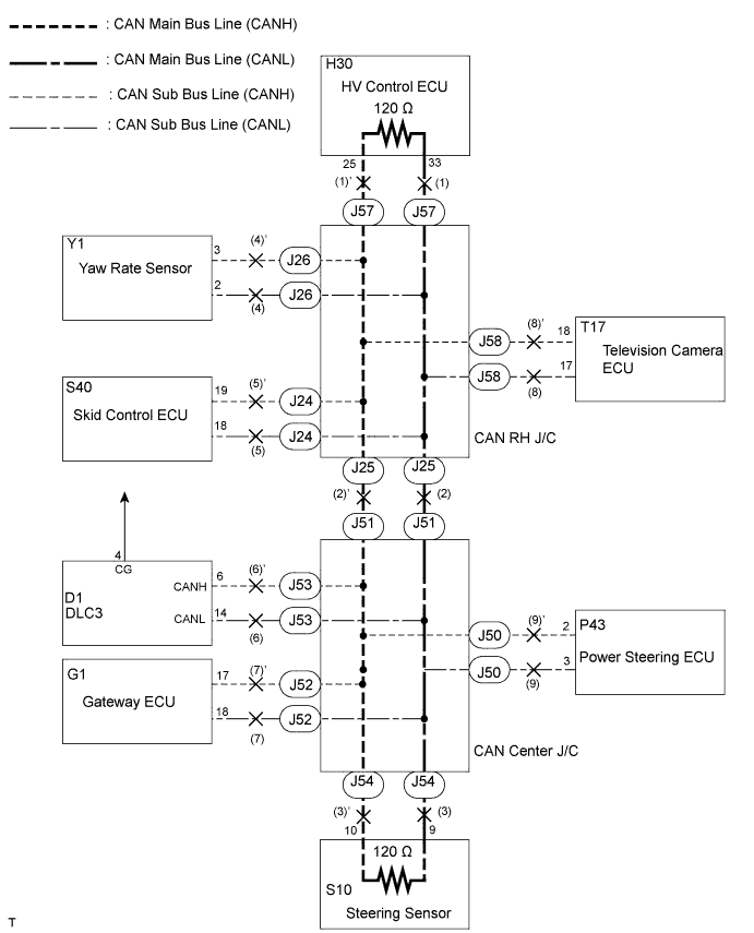

INSPECTION PROCEDURE
| 1. CHECK CAN BUS LINE FOR SHORT TO GND (DLC3 SUB BUS LINE) |

Disconnect the DLC3 sub bus line connector (J53) from the CAN center J/C A side (w/ earth terminal).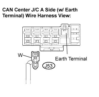
- NOTICE:
- Before disconnecting the connector, make a note of where it is connected.
- Reconnect the connector to its original position.
- Before disconnecting the connector, make a note of where it is connected.
Measure the resistance according to the value(s) in the table below.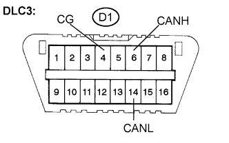
- Standard Resistance:
Tester Connection
Condition
Specified Value
D1-6 (CANH) - D1-4 (CG)
Disconnect the negative auxiliary battery cable
1 MΩ or higher
D1-14 (CANL) - D1-4 (CG)
Disconnect the negative auxiliary battery cable
1 MΩ or higher
|
|
||||

| OK | |
 |
| 2. CONNECT CONNECTOR |
Reconnect the DLC3 sub bus line connector (J53) to the CAN center J/C A side (w/ earth terminal).
| NEXT | |
|
| 3. CHECK CAN BUS LINE FOR SHORT TO GND (CAN BUSES TO D-CAN J/C) |
Disconnect the CAN main bus line connector (J25) from the CAN RH J/C B side (w/o earth terminal).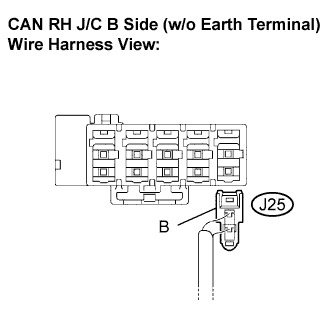
- NOTICE:
- Before disconnecting the connector, make a note of where it is connected.
- Reconnect the connector to its original position.
- Before disconnecting the connector, make a note of where it is connected.
Measure the resistance according to the value(s) in the table below.
- Standard Resistance:
Tester Connection
Condition
Specified Value
D1-6 (CANH) - D1-4 (CG)
Disconnect the negative auxiliary battery cable
1 kΩ or higher
D1-14 (CANL) - D1-4 (CG)
Disconnect the negative auxiliary battery cable
1 kΩ or higher
|
|
||||

| NG | |
|
| 4. CONNECT CONNECTOR |
Reconnect the CAN main bus line connector (J25) to the CAN RH J/C B side (w/o earth terminal).
| NEXT | |
|
| 5. CHECK CAN BUS LINE FOR SHORT TO GND (POWER STEERING ECU SUB BUS LINE) |
Disconnect the power steering ECU sub bus line connector (J50) from the CAN center J/C A side (w/ earth terminal).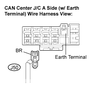
- NOTICE:
- Before disconnecting the connector, make a note of where it is connected.
- Reconnect the connector to its original position.
- Before disconnecting the connector, make a note of where it is connected.
Measure the resistance according to the value(s) in the table below.
- Standard Resistance:
Tester Connection
Condition
Specified Value
D1-6 (CANH) - D1-4 (CG)
Disconnect the negative auxiliary battery cable
1 kΩ or higher
D1-14 (CANL) - D1-4 (CG)
Disconnect the negative auxiliary battery cable
1 kΩ or higher
|
|
||||
| NG | |
|
| 6. CONNECT CONNECTOR |
Reconnect the power steering ECU sub bus line connector (J50) to the CAN center J/C A side (w/ earth terminal).
| NEXT | |
|
| 7. CHECK CAN BUS LINE FOR SHORT TO GND (GATEWAY ECU SUB BUS LINE) |
Disconnect the gateway ECU sub bus line connector (J52) from the CAN center J/C A side (w/o earth terminal).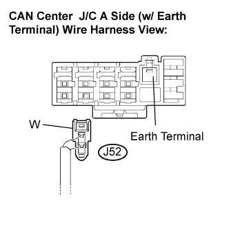
- NOTICE:
- Before disconnecting the connector, make a note of where it is connected.
- Reconnect the connector to its original position.
- Before disconnecting the connector, make a note of where it is connected.
Measure the resistance according to the value(s) in the table below.
- Standard Resistance:
Tester Connection
Condition
Specified Value
D1-6 (CANH) - D1-4 (CG)
Disconnect the negative auxiliary battery cable
1 kΩ or higher
D1-14 (CANL) - D1-4 (CG)
Disconnect the negative auxiliary battery cable
1 kΩ or higher
|
|
||||
| NG | |
|
| 8. CONNECT CONNECTOR |
Reconnect the gateway ECU sub bus line connector (J52) to the CAN center J/C A side (w/ earth terminal).
| NEXT | |
|
| 9. CHECK CAN BUS LINE FOR SHORT TO GND (STEERING SENSOR MAIN BUS LINE) |
Disconnect the steering sensor main bus line connector (J54) from the CAN center J/C B side (w/o earth terminal).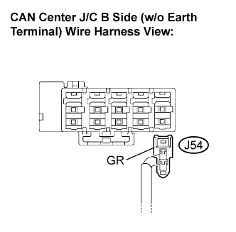
- NOTICE:
- Before disconnecting the connector, make a note of where it is connected.
- Reconnect the connector to its original position.
- Before disconnecting the connector, make a note of where it is connected.
Measure the resistance according to the value(s) in the table below.
- Standard Resistance:
Tester Connection
Condition
Specified Value
D1-6 (CANH) - D1-4 (CG)
Disconnect the negative auxiliary battery cable
1 kΩ or higher
D1-14 (CANL) - D1-4 (CG)
Disconnect the negative auxiliary battery cable
1 kΩ or higher
|
|
||||
| NG | ||
 |
||
| ||
| 10. CONNECT CONNECTOR |
Reconnect the power steering ECU sub bus line connector (J50) to the CAN center J/C A side (w/ earth terminal).
| NEXT | |
|
| 11. CHECK CAN BUS LINE FOR SHORT TO GND (POWER STEERING ECU SUB BUS LINE) |
Disconnect the power steering ECU connector (P43).
Measure the resistance according to the value(s) in the table below.
- Standard Resistance:
Tester Connection
Condition
Specified Value
D1-6 (CANH) - D1-4 (CG)
Disconnect the negative auxiliary battery cable
1 kΩ or higher
D1-14 (CANL) - D1-4 (CG)
Disconnect the negative auxiliary battery cable
1 kΩ or higher
|
|
||||
| NG | ||
|
||
| ||
| 12. CONNECT CONNECTOR |
Reconnect the gateway ECU sub bus line connector (J52) to the CAN center J/C A side (w/ earth terminal).
| NEXT | |
|
| 13. CHECK CAN BUS LINE FOR SHORT TO GND (GATEWAY ECU SUB BUS LINE) |
Disconnect the gateway connector (G1).
Measure the resistance according to the value(s) in the table below.
- Standard Resistance:
Tester Connection
Condition
Specified Value
D1-6 (CANH) - D1-4 (CG)
Disconnect the negative auxiliary battery cable
1 kΩ or higher
D1-14 (CANL) - D1-4 (CG)
Disconnect the negative auxiliary battery cable
1 kΩ or higher
|
|
||||
| NG | ||
|
||
| ||
| 14. CONNECT CONNECTOR |
Reconnect the steering sensor main bus line connector (J54) to the CAN center J/C B side (w/o earth terminal).
| NEXT | |
|
| 15. CHECK CAN BUS LINE FOR SHORT TO GND (STEERING SENSOR MAIN BUS LINE) |
Disconnect the steering sensor connector (S10).
Measure the resistance according to the value(s) in the table below.
- Standard Resistance:
Tester Connection
Condition
Specified Value
D1-6 (CANH) - D1-4 (CG)
Disconnect the negative auxiliary battery cable
1 kΩ or higher
D1-14 (CANL) - D1-4 (CG)
Disconnect the negative auxiliary battery cable
1 kΩ or higher
|
|
||||
| OK | ||
|
||
| ||
| 16. CONNECT CONNECTOR |
Reconnect the CAN main bus line connector (J25) to the CAN RH J/C B side (w/o earth terminal).
| NEXT | |
|
| 17. CHECK CAN BUS LINE FOR SHORT TO GND (SKID CONTROL ECU SUB BUS LINE) |
Disconnect the skid control ECU sub bus line connector (J24) from the CAN RH J/C A side (w/ earth terminal).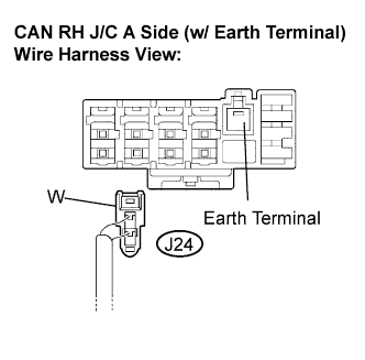
- NOTICE:
- Before disconnecting the connector, make a note of where it is connected.
- Reconnect the connector to its original position.
- Before disconnecting the connector, make a note of where it is connected.
Measure the resistance according to the value(s) in the table below.
- Standard Resistance:
Tester Connection
Condition
Specified Value
D1-6 (CANH) - D1-4 (CG)
Disconnect the negative auxiliary battery cable
1 kΩ or higher
D1-14 (CANL) - D1-4 (CG)
Disconnect the negative auxiliary battery cable
1 kΩ or higher
|
|
||||
| NG | |
|
| 18. CONNECT CONNECTOR |
Reconnect the skid control ECU sub bus line connector (J24) to the CAN RH J/C A side (w/ earth terminal).
| NEXT | |
|
| 19. CHECK CAN BUS LINE FOR SHORT TO GND (TELEVISION CAMERA ECU SUB BUS LINE) |
Disconnect the television camera ECU sub bus line connector (J58) from the CAN RH J/C B side (w/o earth terminal).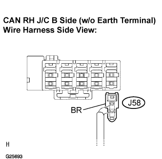
- NOTICE:
- Before disconnecting the connector, make a note of where it is connected.
- Reconnect the connector to its original position.
- Before disconnecting the connector, make a note of where it is connected.
Measure the resistance according to the value(s) in the table below.
- Standard Resistance:
Tester Connection
Condition
Specified Value
D1-6 (CANH) - D1-4 (CG)
Disconnect the negative auxiliary battery cable
1 kΩ or higher
D1-14 (CANL) - D1-4 (CG)
Disconnect the negative auxiliary battery cable
1 kΩ or higher
|
|
||||
| NG | |
|
| 20. CONNECT CONNECTOR |
Reconnect the television camera ECU sub bus line connector (J58) to the CAN RH J/C B side (w/o earth terminal).
| NEXT | |
|
| 21. CHECK CAN BUS LINE FOR SHORT TO GND (YAW RATE SENSOR ECU SUB BUS LINE) |
Disconnect the yaw rate sensor sub bus line connector (J26) from the CAN RH J/C B side (w/o earth terminal).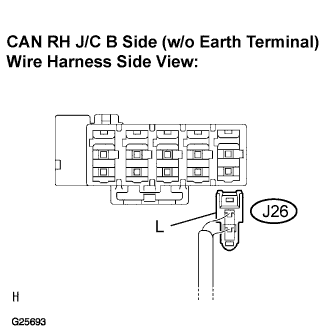
- NOTICE:
- Before disconnecting the connector, make a note of where it is connected.
- Reconnect the connector to its original position.
- Before disconnecting the connector, make a note of where it is connected.
Measure the resistance according to the value(s) in the table below.
- Standard Resistance:
Tester Connection
Condition
Specified Value
D1-6 (CANH) - D1-4 (CG)
Disconnect the negative auxiliary battery cable
1 kΩ or higher
D1-14 (CANL) - D1-4 (CG)
Disconnect the negative auxiliary battery cable
1 kΩ or higher
|
|
||||
| NG | |
|
| 22. CONNECT CONNECTOR |
Reconnect the yaw rate sensor sub bus line connector (J26) to the CAN RH J/C B side (w/o earth terminal).
| NEXT | |
|
| 23. CHECK CAN BUS LINE FOR SHORT TO GND (HV CONTROL ECU MAIN BUS LINE) |
Disconnect the HV control ECU main bus line connector (J57) from the CAN RH J/C B side (w/o earth terminal).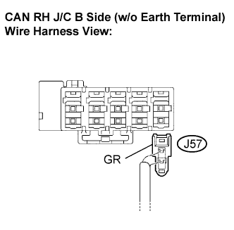
- NOTICE:
- Before disconnecting the connector, make a note of where it is connected.
- Reconnect the connector to its original position.
- Before disconnecting the connector, make a note of where it is connected.
Measure the resistance according to the value(s) in the table below.
- Standard Resistance:
Tester Connection
Condition
Specified Value
D1-6 (CANH) - D1-4 (CG)
Disconnect the negative auxiliary battery cable
1 kΩ or higher
D1-14 (CANL) - D1-4 (CG)
Disconnect the negative auxiliary battery cable
1 kΩ or higher
|
|
||||
| NG | ||
|
||
| ||
| 24. CONNECT CONNECTOR |
Reconnect the skid control ECU sub bus line connector (J24) to the CAN RH J/C A side (w/ earth terminal).
| NEXT | |
|
| 25. CHECK CAN BUS LINE FOR SHORT TO GND (SKID CONTROL ECU SUB BUS LINE) |
Disconnect the skid control ECU connector (S40).
Measure the resistance according to the value(s) in the table below.
- Standard Resistance:
Tester Connection
Condition
Specified Value
D1-6 (CANH) - D1-4 (CG)
Disconnect the negative auxiliary battery cable
1 kΩ or higher
D1-14 (CANL) - D1-4 (CG)
Disconnect the negative auxiliary battery cable
1 kΩ or higher
|
|
||||
| NG | ||
|
||
| ||
| 26. CONNECT CONNECTOR |
Reconnect the television camera ECU sub bus line connector (J58) to the CAN RH J/C B side (w/o earth terminal).
| NEXT | |
|
| 27. CHECK CAN BUS LINE FOR SHORT TO GND (TELEVISION CAMERA ECU SUB BUS LINE) |
Disconnect the television camera ECU connector (T17).
Measure the resistance according to the value(s) in the table below.
- Standard Resistance:
Tester Connection
Condition
Specified Value
D1-6 (CANH) - D1-4 (CG)
Disconnect the negative auxiliary battery cable
1 kΩ or higher
D1-14 (CANL) - D1-4 (CG)
Disconnect the negative auxiliary battery cable
1 kΩ or higher
|
|
||||
| NG | ||
|
||
| ||
| 28. CONNECT CONNECTOR |
Reconnect the yaw rate sensor sub bus line connector (J26) to the CAN RH J/C B side (w/o earth terminal).
| NEXT | |
|
| 29. CHECK CAN BUS LINE FOR SHORT TO GND (YAW RATE SENSOR SUB BUS LINE) |
Disconnect the yaw rate sensor connector (Y1).
Measure the resistance according to the value(s) in the table below.
- Standard Resistance:
Tester Connection
Condition
Specified Value
D1-6 (CANH) - D1-4 (CG)
Disconnect the negative auxiliary battery cable
1 kΩ or higher
D1-14 (CANL) - D1-4 (CG)
Disconnect the negative auxiliary battery cable
1 kΩ or higher
|
|
||||
| NG | ||
|
||
| ||
| 30. CONNECT CONNECTOR |
Reconnect the HV control ECU main bus line connector (J57) to the CAN RH J/C B side (w/o earth terminal).
| NEXT | |
|
| 31. CHECK CAN BUS LINE FOR SHORT TO GND (HV CONTROL ECU MAIN BUS LINE) |
Disconnect the HV control ECU connector (H30).
Measure the resistance according to the value(s) in the table below.
- Standard Resistance:
Tester Connection
Condition
Specified Value
D1-6 (CANH) - D1-4 (CG)
Disconnect the negative auxiliary battery cable
1 kΩ or higher
D1-14 (CANL) - D1-4 (CG)
Disconnect the negative auxiliary battery cable
1 kΩ or higher
|
|
||||
| NG | ||
|
||
| ||