Rear Window Defogger System does not Operate
Circuit diagnosis
DESCRIPTION
- The rear defogger & mirror heater switch on the multi-display inputs a request signal to the A/C amplifier (ECU). Then, the A/C amplifier turns ON the RR-DEF relay built into the power distributor in response to the input, thus switching ON the rear defogger. (The deicer and mirror heater also turn ON at the same time)
- HINT:
- The power distributor is built into the J/B No.2.
- The RR-DEF relay is built into the J/B No.2. For inspection, use the terminals in the J/B No.2.
- If RR-DEF relay is malfunctioning , replace the J/B No.2.
WIRING DIAGRAM
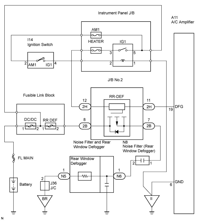

INSPECTION PROCEDURE
| 1. INSPECT COMMUNICATION LINE |

Use the intelligent tester to check for normal function of the multiplex communication system.
(ECU unconnected, communication line malfunctioning) Without DTC B1214, B1215 or B 1262 outputs, proceed to A.
(ECU unconnected, communication line malfunctioning) With DTC B1214, B1215 or B 1262 outputs, proceed to B.
|
|
||||

| A | |
 |
| 2. INSPECT FUSE (HEATER, RR-DEF) |
Remove the HEATER fuse from the instrument panel J/B.
Remove the RR-DEF fuse from the FL block.
Check the resistance.
- Standard resistance:
- Below 1 Ω
|
|
||||
| OK | |
|
| 3. PERFORM ACTIVE TEST |
Connect the intelligent tester (with CAN VIN) to the DLC3.
Turn the ignition switch on.
Perform the ACTIVE TEST according to the display on the tester.
| Item |
Test Details |
Diagnostic Note |
| DEFOGGER RLY-R |
Operate rear window defogger OFF/ON |
- |
|
|
||||

| OK | |
|
| 4. CHECK AIR CONDITIONING SYSTEM OPERATE |
|
|
||||
| OK | ||
 |
||
| ||
| 5. INSPECT JUNCTION BLOCK |
Check the voltage of the terminal of the J/B.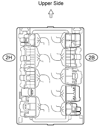
- Standard voltage:
Tester Connection
Switch Position
Specified Condition
2H-12 - Body Ground
Ignition switch ON
10 to 14 V
2H-12 - Body Ground
Ignition switch OFF
Below 1 V
2B-8 - Body Ground
Always
10 to 14 V
|
|
||||
| OK | |
|
| 6. INSPECT JUNCTION BLOCK (MODE MONITOR TERMINAL) |
Check the voltage of the terminal to the following condition.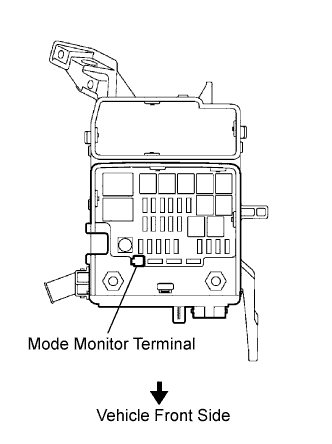
- Engine running.
- A/C switch is OFF.
- Rear defogger and deicer switch is ON.
- Result:
Result
Proceed to
More than 5 V
A
Below 2 V
B
- Engine running.
|
|
||||
| A | |
|
| 7. INSPECT JUNCTION BLOCK (RR-DEF RELAY) |
Remove the junction block No.2.
Connect the battery positive (+) lead to terminal 2B-8 and battery negative (-) terminal lead to terminal 2H-12, 2B-7 and 2H-11.
Check the voltage of the RR-DEF relay terminals.
- Standard voltage:
Tester Connection
Condition
Specified Condition
2B-7 - 2H-12
Always
Below 1 V
Connect another battery positive (+) lead to the terminal 2H-12.
Check the voltage of the RR-DEF relay terminals.
- Standard voltage:
Tester Connection
Condition
Specified Condition
2B-7 - 2H-12
Ignition switch ON
Below 1 V
2B-7 - 2H-12
Ignition switch OFF
10 to 14 V
|
|
||||
| OK | |
|
| 8. INSPECT AIR CONDITIONING AMPLIFIER ASSEMBLY |
Disconnect the A11 connector.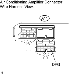
Measure the voltage according to the value(s) in the table below.
- Standard voltage:
Tester connection
Condition
Specified condition
A11-19 (DFG) - Body ground
Ignition switch: ON
10 to 14 V
A11-19 (DFG) - Body ground
Ignition switch: OFF
Below 1 V
|
|
||||
| OK | |
|
| 9. INSPECT AIR CONDITIONING AMPLIFIER ASSEMBLY |
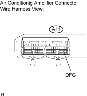 |
Connect the A11 connector.
Connect the intelligent tester to the DLC3.
Measure the voltage according to the value(s) in the table below.
- Standard voltage:
Tester connection
Intelligent tester condition
Specified condition
A11-19 (DFG) - Body ground
ACTIVE TEST: ON (*1)
10 to 14 V
A11-19 (DFG) - Body ground
ACTIVE TEST: OFF (*1)
Below 1 V
- HINT:
- *1: Perform the ACTIVE TEST according to the display on the tester.
A/C amplifier assembly (A/C ECU) Item
Test Details
Diagnostic Note
DEFOGGER RLY-R
Operate rear window defogger OFF/ON
-
|
|
||||
| OK | |
|
| 10. INSPECT REAR WINDOW DEFOGGER WIRE |
- NOTICE:
- When cleaning the glass, wipe the glass along the wire using a soft and dry cloth. Take care not to damage the wires.
- Do not use detergents or glass cleaners that have abrasive ingredients.
-
When measuring voltage, wrap a piece of tin foil around the tip of the negative tester probe and press the foil against the wire with your finger, as shown in the illustration.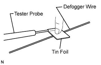
- When cleaning the glass, wipe the glass along the wire using a soft and dry cloth. Take care not to damage the wires.
Turn the ignition switch on.
Turn the defogger switch ON.
Check the voltage at the center of each defogger wire, as shown in the illustration.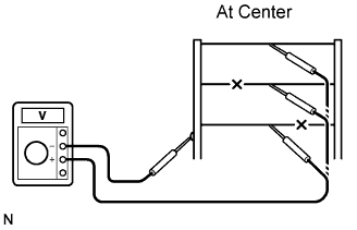
- Standard voltage:
Voltage
Criteria
Approx .5 V
Wire is not broken
Approx. 10 or 0 V
Wire is broken
- HINT:
- If there is approximately 10 V, the wire may be broken between the center of the wire and the wire end on the battery side. If there is no voltage, the wire may be broken between the center of the wire and the end on the ground side.
Place the voltmeter positive (+) lead against the defogger wire on the battery side.
Place the voltmeter negative (-) lead with the foil strip against the wire on the ground side.
Slide the positive (+) lead from the battery side to the ground side.
The point where the voltage drops from approximately 10 V to 0 V is where the defogger wire is broken.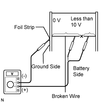
- HINT:
- If the defogger wire is not broken, the voltmeter indicates 0 V at the positive (+) end of the defogger wire but gradually increases to approximately 12 V as the meter probe moves to the other end.
|
|
||||
| OK | |
|
| 11. CHECK WIRE HARNESS (REAR WINDOW DEFOGGER - JUNCTION BLOCK NO.2) |
Disconnect the N6, N5 defogger and 2B J/B connectors.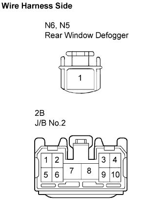
Check the resistance of the wire harness side connectors.
- Standard resistance:
Tester Connection
Specified Condition
N6-1 - 2B-7
Below 1 Ω
N6-1 -Body ground
10 kΩ or higher
N5-1 - Body ground
Below 1 Ω
N5-1 - 2B-7
10 kΩ or higher
|
|
||||
| OK | ||
|
||
| ||
| 12. CHECK WIRE HARNESS (REAR WINDOW DEFOGGER - JUNCTION BLOCK NO.2) |
Disconnect the N6, N5 defogger and 2B J/B connectors.
Check the resistance of the wire harness side connectors.
- Standard resistance:
Tester Connection
Specified Condition
N6-1 - 2B-7
Below 1 Ω
N6-1 -Body ground
10 kΩ or higher
N5-1 - Body ground
Below 1 Ω
N5-1 - 2B-7
10 kΩ or higher
|
|
||||
| OK | |
|
| 13. INSPECT JUNCTION BLOCK (RR-DEF RELAY) |
Remove the junction block No.2.
Connect the battery positive (+) lead to terminal 2B-8 and battery negative (-) terminal lead to terminal 2H-12, 2B-7 and 2H-11.
Check the voltage of the RR-DEF relay terminals.
- Standard voltage:
Tester Connection
Condition
Specified Condition
2B-7 - 2H-12
Always
Below 1 V
Connect another battery positive (+) lead to the terminal 2H-12.
Check the voltage of the RR-DEF relay terminals.
- Standard voltage:
Tester Connection
Condition
Specified Condition
2B-7 - 2H-12
Ignition switch ON
10 to 14 V
2B-7 - 2H-12
Ignition switch OFF
Below 1 V
|
|
||||
| OK | ||
|
||
| ||