B1272 Position control ECU and switch assembly (driver seat ECU) communication stops
Diagnostic trouble codes
DESCRIPTION
This DTC is detected when communication between the position control ECU and switch (driver seat ECU) and multiplex network gateway ECU stops for more than 10 seconds.| DTC No. |
DTC Detection Condition |
Trouble Area |
| B1272 |
Position control ECU and switch assembly (driver seat ECU) communication stops |
|
WIRING DIAGRAM
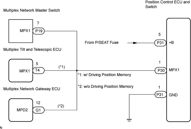

INSPECTION PROCEDURE
- HINT:
- When "+B of GND short malfunction of communication bus" DTCs (B1214 and B1215) are detected at the same time as "communication stop" DTC B1272, repair the "+B or GND short malfunction of communication bus" DTCs first.
| 1. CHECK OPERATION |

Check that the switch of the front power seat can move the driver side seat normally.
- HINT:
- With this inspection, the position control ECU & switch assembly (driver seat ECU) CPU can be diagnosed if it works normally or not.
- OK:
- Switch of the front power seat can move driver side seat normally.
|
|
||||

| NG | |
 |
| 2. INSPECT FUSE (P/SEAT) |
Remove the P/SEAT fuse from the instrument panel junction block.
Measure the resistance of the fuse.
- Standard resistance:
- Below 1 Ω
|
|
||||

| OK | |
|
| 3. CHECK WIRE HARNESS (POSITION CONTROL ECU AND SWITCH ASSEMBLY (DRIVER SEAT ECU) - BATTERY AND BODY GROUND) |
Disconnect the P31 ECU connector.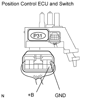
Measure the resistance and voltage of the wire harness side connector.
- Standard voltage:
Tester Connection
Specified Condition
P31-5 (+B) - Body ground
10 to 14 V
- Standard resistance:
Tester Connection
Specified Condition
P31-1 (GND) - Body ground
Below 1 Ω
|
|
||||
| OK | |
|
| 4. CHECK RESISTANCE OF COMMUNICATION LINE |
Disconnect the P30, P19 and T4 ECU connectors (w/ Driving position memory).
Disconnect the P30, P19 and G3 ECU connectors (w/o Driving position memory).
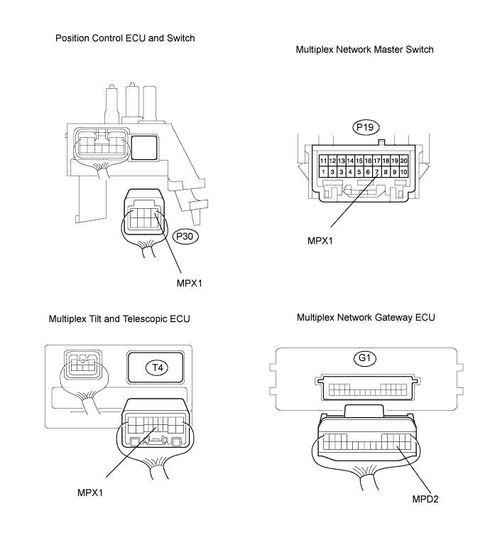
Measure the resistance of the wire harness side connectors.
- Standard resistance:
Tester Connection
Specified Condition
P30-1 (MPX1) - T4-5 (MPX1) (*1)
Below 1 Ω
P30-1 (MPX1) - P19-7 (MPX1)
Below 1 Ω
P30-1 (MPX1) - G1-12 (MPD2) (*2)
Below 1 Ω
|
|
||||
| OK | ||
 |
||
| ||