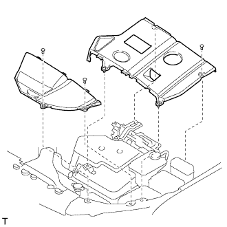
INSTALLATION
Removal / installation
| 1. INSTALL RADIATOR ASSEMBLY |

Install the radiator assembly with the 4 bolts to the cooler condenser assembly.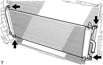

- Torque:
- 5.0 N*m{ 51 kgf*cm , 44 in.*lbf }
Connect the 2 water hoses with the 2 clamps to the radiator assembly.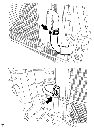
| 2. INSTALL HOOD LOCK SUPPORT SUB-ASSEMBLY |
Install the hood lock support sub-assembly with the bolt.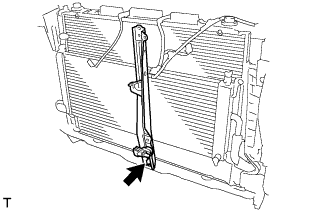
- Torque:
- 7.0 N*m{ 71 kgf*cm , 62 in.*lbf }
| 3. INSTALL RADIATOR SUPPORT SUB-ASSEMBLY UPPER |
Install the radiator support upper with the 5 boits.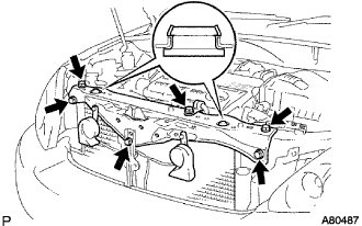
- Torque:
- 7.0 N*m{ 71 kgf*cm , 62 in.*lbf }
- NOTICE:
- Secure the upper member with the retaining claws of the radiator upper support.
Connect the horn connector.
Install the suction tube bracket with the bolt .
- Torque:
- 9.8 N*m{ 100 kgf*cm , 87 in.*lbf }
| 4. INSTALL HOOD LOCK ASSEMBLY |
Install the hood lock assembly with the 2 bolts and nut.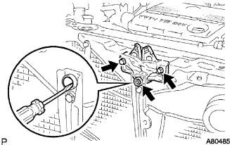
- Torque:
- 8.0 N*m{ 82 kgf*cm , 71 in.*lbf }
Attach the claws and install the hood lock control cable cover.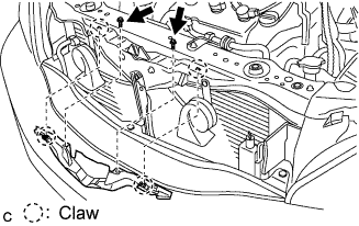
Install the 2 screws.
| 5. INSTALL AIR CLEANER CAP W/INLET |
Install the air cleaner filter element to the air cleaner case.
Install the 2 bolts, 4 clamps and air cleaner cap w/ inlet.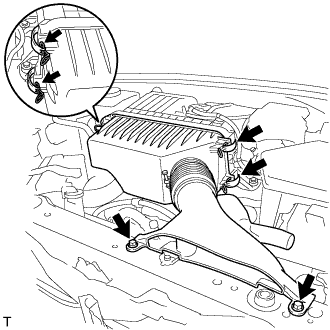
- Torque:
- 7.0 N*m{ 71 kgf*cm , 62 in.*lbf }
| 6. INSTALL COOL AIR INTAKE DUCT SEAL |
Install the 4 clips and cool air intake duct seal.
| 7. INSTALL FRONT BUMPER REINFORCEMENT |
Install the front bumper reinforcement with the 6 bolts.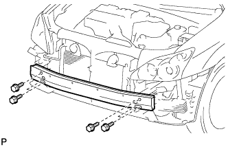
- Torque:
- 77 N*m{ 785 kgf*cm , 57 ft.*lbf }
| 8. INSTALL FRONT BUMPER ENERGY ABSORBER |
| 9. INSTALL FRONT BUMPER COVER |
| 10. INSTALL FRONT BUMPER STAY CENTER |
| 11. INSPECT HOOD SUB-ASSEMBLY |
Check that the clearance is within the standard range.
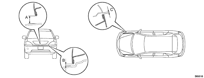
Standard range: A
6.0 +- 1.5 mm (0.236 +- 0.059 in.)
B
6.0 +- 1.5 mm (0.236 +- 0.059 in.)
C
4.0 +- 1.5 mm (0.157 +- 0.059 in.)
| 12. ADJUST HOOD SUB-ASSEMBLY |
Horizontally and vertically adjust the hood.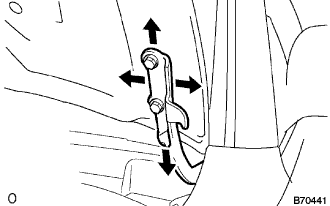
Loosen the 4 hood hinge mounting bolts on the hood side.
Adjust the clearance by moving the hood, so that it will be in the standard range.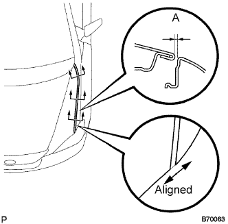
- Standard range A:
- 4.0 +- 1.5 mm (0.157 +- 0.059 in.)
Tighten the hood side hinge bolts after the adjustment.
- Torque:
- 13 N*m{ 133 kgf*cm , 10 ft.*lbf }
Adjust the height of the hood front end using the cushion rubber.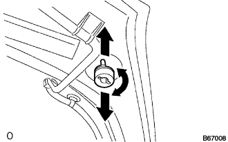
Adjust the cushion rubber so that the hood and the fender will be aligned.
- HINT:
- The cushion rubber moves up and down when turned.
Adjust the hood lock.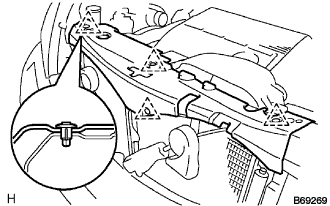
Remove the 4 clips and cool air intake duct seal.
Remove the 2 screws, disengage the 2 claws and remove the hood lock control cable cover.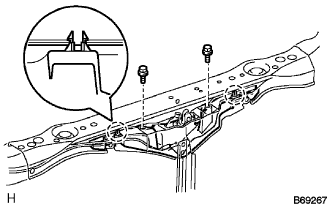
- HINT:
- If the cover is damaged, replace it with a new cover.
Using a screwdriver wrapped with protective tape, remove the nut cap.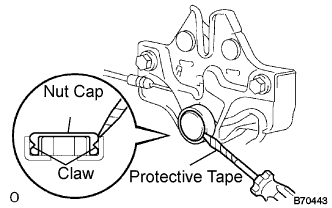
- NOTICE:
- Removing the nut cap damages the claw inside the nut cap. Therefore, the use of a new nut cap is necessary for installation.
Loosen the 3 bolts.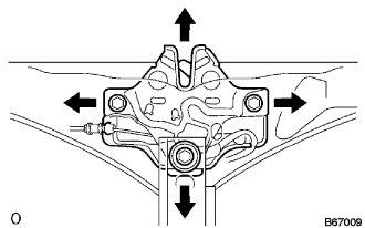
Adjust the hood lock position by moving the striker, so that the striker can enter smoothly.
- Torque:
- 8.0 N*m{ 82 kgf*cm , 71 in.*lbf }
- HINT:
- Perform this procedure after replacement of the centering bolt with the supplied one.
| 13. ADD HYBRID VEHICLE COOLANT |
Loosen the bleeder plug shown in the illustration and connect a hose.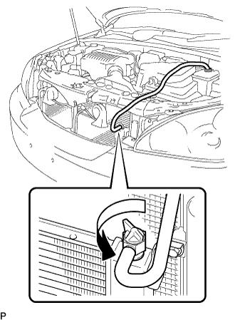
- NOTICE:
- Insert one end of the hose into the reserve tank.
Add coolant from the reserve tank.
Add coolant until the level of coolant in the hose attached to the bleeder plug reaches the same level as the FULL line of the reserve tank.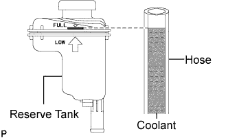
- Coolant quantity:
- 3.4 L (3.6 US qts, 3.0 Imp. qts.)
When using the intelligent tester:
Connect the intelligent tester to the DLC3.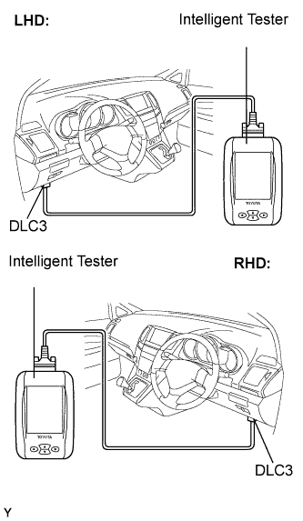
Turn the ignition switch to the ON position.
Select the inspection mode (Click here).
On the tester, enter the following menus: Powertrain / Hybrid Control / Active test / Water Pump.
Keep the coolant at the FULL level in the reserve tank to compensate for the drop in coolant level when the air bleeds.
- Standard:
- Air bleeding from the coolant system is completed when the noise made by the water pump becomes smaller and the circulation of coolant in the reserve tank improves.
- HINT:
- Loud noise made by the water pump and poor circulation of coolant in the reserve tank indicates that there is air in the coolant system.
When not using the intelligent tester:
Put the vehicle into the READY-on state. [*1]
Turn the ignition switch off and add coolant to the FULL level because the coolant level drops as the air bleeds. [*2]
- NOTICE:
- Be sure to turn the ignition switch off before adding LLC.
- Do not work on the components in the engine compartment while the vehicle is in the READY-on state because the engine is in intermittent operation.
- Be sure to turn the ignition switch off before adding LLC.
Repeat steps [*1] and [*2] until air bleeding from the coolant system is completed.
- Standard:
- Air bleeding from the coolant system is completed when the noise made by the water pump becomes smaller and the circulation of coolant in the reserve tank improves.
- HINT:
- Loud noise made by the water pump and poor circulation of coolant in the reserve tank indicates that there is air in the coolant system.
When the air is completely bled from the coolant system, tighten the plug.
Add coolant to the FULL mark of the reserve tank.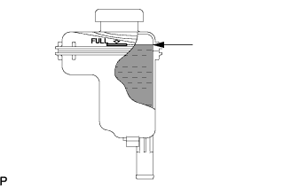
| 14. CHECK HYBRID VEHICLE COOLANT LEAKS |
| 15. INSTALL ENGINE ROOM SIDE LH COVER |
Fit the clips and install the engine room side LH cover.