INSTALLATION
Removal / installation
| 1. INSTALL KNOCK CONTROL SENSOR |

Install the 2 knock sensors so that it is horizontal as shown in the illustration. Then install the 2 bolts.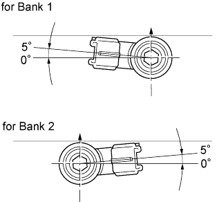

- Torque:
- 20 N*m{ 199 kgf*cm , 15 ft.*lbf }
- HINT:
- It is acceptable for the sensor to be tilted 5°.
Connect the 2 knock sensor connectors.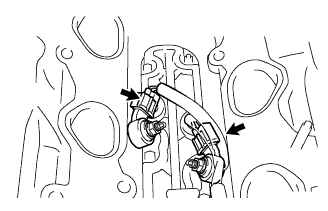
| 2. INSTALL WATER OUTLET |
Install 2 new gaskets to the 2 cylinder heads.
Install the water outlet together with water by-pass hose No.1 and unlock the hose clamp.
Tighten the 2 bolts, 2 nuts and 2 washers.
- Torque:
- 15 N*m{ 153 kgf*cm , 11 ft.*lbf }
Install the clamp.
Connect the engine coolant temperature sensor connector.
Connect the radiator hose inlet.
| 3. INSTALL INTAKE MANIFOLD |
Install the intake manifold with the 9 bolts, 2 nuts and 2 washers. Using several steps, tighten the bolts and nuts uniformly in the sequence shown in the illustration.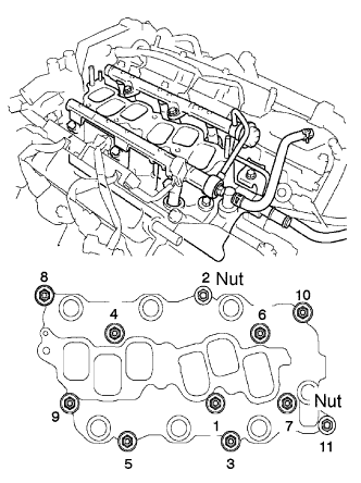
- Torque:
- 15 N*m{ 153 kgf*cm , 11 ft.*lbf }
Retighten the water outlet mounting bolts and nuts.
- Torque:
- 15 N*m{ 153 kgf*cm , 11 ft.*lbf }
Connect the 6 fuel injector connectors.
Install the ground cable with the nut.
- Torque:
- 8.4 N*m{ 86 kgf*cm , 74 in.*lbf }
| 4. CONNECT RADIATOR HOSE INLET |
Connect the radiator hose inlet.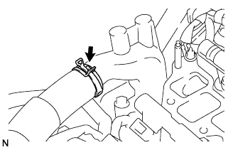
| 5. CONNECT HEATER WATER INLET HOSE |
Connect the heater water inlet hose.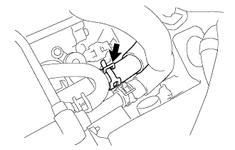
| 6. CONNECT FUEL PIPE SUB-ASSEMBLY |
Align the quick connector with the pipe, then push in the quick connector until the retainer makes a "click" sound to connect the fuel hose to the fuel pipe.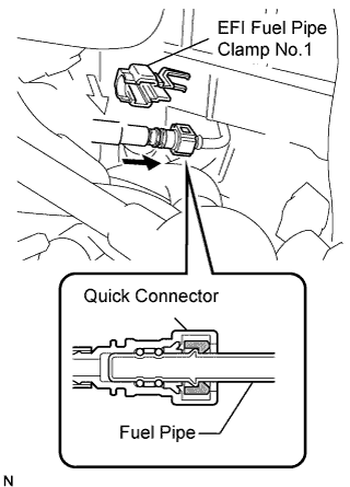
- NOTICE:
- Check that there are no scratches or foreign objects around the connected part of the quick connector and pipe before this work.
- After connecting the fuel hose, confirm that it is securely connected by pulling the quick connector.
- Check that there are no scratches or foreign objects around the connected part of the quick connector and pipe before this work.
Install the fuel pipe clamp No.1.
| 7. INSTALL INTAKE AIR SURGE TANK |
Install a new gasket to the intake air surge tank.
Using a socket hexagon wrench 8 mm, install the intake manifold with the 4 bolts and 2 nuts . Using several steps, tighten the bolts and nuts uniformly in the sequence shown in the illustration.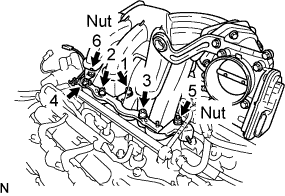
- Torque:
- 28 N*m{ 286 kgf*cm , 21 ft.*lbf }
Connect the ground cable connector.
Install the surge tank stay No. 2 (A) with the 2 bolts.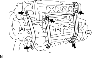
- Torque:
- 20 N*m{ 199 kgf*cm , 14 ft.*lbf }
Install the surge tank stay No. 1 (B) with the 2 bolts.
- Torque:
- 20 N*m{ 199 kgf*cm , 14 ft.*lbf }
Install the engine hunger No. 1 (C) with the 2 bolts.
- Torque:
- 20 N*m{ 199 kgf*cm , 14 ft.*lbf }
Connect the ventilation hose.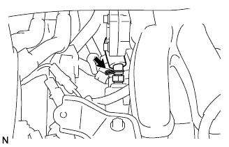
Connect the fuel vapor feed hose (A).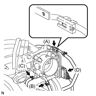
Connect the water by-pass hose No.3 (B).
Connect the water by-pass hose No.2 (C).
Connect the throttle motor connector (D).
| 8. INSTALL EMISSION CONTROL VALVE SET |
Install the emission control valve set with the 2 nuts (A).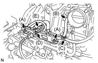
- Torque:
- 8.0 N*m{ 82 kgf*cm , 71 in.*lbf }
Connect the fuel vapor feed hose No.2 (B).
Connect the fuel vapor feed hose No.1 (C).
Connect the wire harness clamp (D).
Connect the VSV connector (E).
| 9. INSTALL ENGINE MOVING CONTROL ROD |
Temporarily tighten bolts B and C.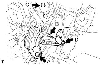
First tighten bolt A, bolt B, then bolt C in this order.
- Torque:
- 64 N*m{ 653 kgf*cm , 47 ft.*lbf }
Tighten bolt D.
- Torque:
- 23 N*m{ 235 kgf*cm , 17 ft.*lbf }
| 10. INSTALL AIR CLEANER BRACKET |
Install the 2 bolts and air cleaner bracket.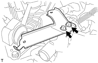
- Torque:
- 27 N*m{ 275 kgf*cm , 20 ft.*lbf }
| 11. INSTALL RESERVOIR BRACKET |
Install the 2 bolts, nut and reservoir bracket.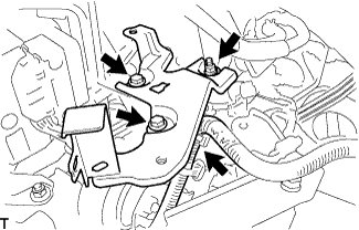
- Torque:
- 9.0 N*m{ 92 kgf*cm , 80 in.*lbf }
Connect the clamp.
| 12. INSTALL BRAKE MASTER CYLINDER RESERVOIR SUB-ASSEMBLY |
Install the 2 bolts and brake master cylinder reservoir to the bracket.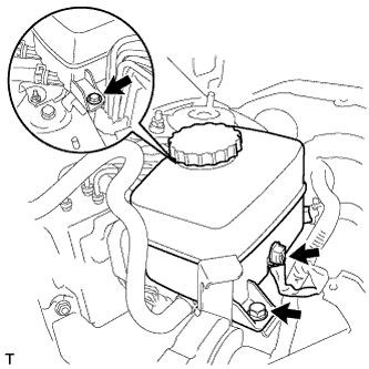
- Torque:
- 9.0 N*m{ 92 kgf*cm , 80 in.*lbf }
Connect the connector.
| 13. INSTALL AIR CLEANER CASE W/ RESONATOR |
Install the air cleaner hose No.1 to the throttle body assembly with the hose clamp.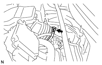
Install the air cleaner case w/ resonator with the 5 bolts.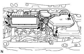
- Torque:
- 5.0 N*m{ 51 kgf*cm , 44 in.*lbf }
Connect the MAF meter connector.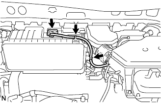
Connect the 2 wire harness clamps to the air cleaner.
Connect the ventilation hose No.2.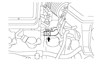
| 14. INSTALL AIR CLEANER CAP W/ INLET |
Install a new air cleaner element to the air cleaner case.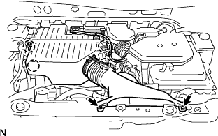
Install the air cleaner cap w/ inlet with the 4 clamps.
Install the air cleaner cap w/ inlet with the 2 bolts.
- Torque:
- 7.0 N*m{ 71 kgf*cm , 62 in.*lbf }
| 15. INSTALL COOL AIR INTAKE DUCT SEAL |
Install the 4 clips and cool air intake duct seal.
| 16. ADD COOLANT |
Tighten the lower drain plug of the radiator.
Loosen the upper drain plug of the radiator.
Install a vinyl tube to the vent plug located on the upper drain plug.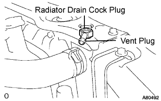
Fill the radiator with engine coolant until the vinyl tube is filled with the coolant.
Tighten the upper drain plug.
- CAUTION:
- Do not use an alcohol type coolant or plain water alone.
- The coolant must be mixed with plain water (preferably de-mineralized water).
- Capacity:
- 9.7 liters (10.3 US qts, 8.5 lmp.qts)
- Do not use an alcohol type coolant or plain water alone.
- HINT:
- Improper coolants may damage engine cooling system.
- Use "Toyota Long Life Coolant" or equivalent. Mix it with plain water according to the manufacturer's instruction.
- Using of coolant which includes more than 50% (freezing protection down to -35°C (-31°F) or 60% (freezing protection down to -50°C (-58°F) of ethylene-glycol is recommended but not more than 70%.
- Observe the coolant level inside the radiator by pressing the inlet and outlet radiator hoses several times by hand. If the coolant level goes down, add the coolant.
- Improper coolants may damage engine cooling system.
Install the radiator cap securely.
Fill the radiator reservoir tank with coolant.
Warm up the engine.
- HINT:
- Press the inlet and outlet radiator hoses several times by hand while warming up the engine.
Stop the engine and wait until the coolant cools down.
Remove the radiator cap and check the coolant level inside the radiator.
If the coolant level is below the full level, perform the steps from (a) through (j) and repeat the operation until the coolant level stays the full level.
Recheck the coolant level inside the radiator reservoir tank. If it is below the full level, add the coolant.
| 17. CONNECT CABLE TO NEGATIVE BATTERY TERMINAL |
| 18. CHECK FOR ENGINE COOLANT LEAKS |
 |
- CAUTION:
- Do not remove the radiator cap while the engine and radiator are still hot. Thermal expansion will cause hot engine coolant and steam to blow out from the radiator.
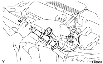
Fill the radiator with coolant and attach a radiator cap tester.
Warm up the engine.
Using a radiator cap tester, increase the pressure inside the radiator to 118 kPa (1.2 kgf*cm, 17 psi), and check that the pressure does not drop.
If the pressure drops, check the hoses, radiator and water pump for leaks. If no external leaks are found, check the heater core, cylinder block and cylinder head.
| 19. CHECK FOR FUEL LEAKS |
Connect the intelligent tester to the DLC3.
Turn the ignition switch to the ON position and turn the intelligent tester on.
- NOTICE:
- Do not start the engine.
Select the Active Test mode on the intelligent tester to operate the fuel pump.
- HINT:
- Refer to the intelligent tester operator's manual for further details.
Check that there are no fuel leaks anywhere in the fuel system after performing maintenance.
| 20. INSTALL COWL TOP PANEL SUB-ASSEMBLY OUTER |
Remove the 4 shock absorber nuts.
Install the 4 bolts, 2 nuts and cowl top panel sub-assembly.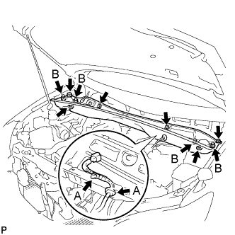
- Torque:
- 5.0 N*m{ 51 kgf*cm , 44 in.*lbf }
Install the 4 shock absorber nuts (B).
- Torque:
- 80 N*m{ 815 kgf*cm , 59 ft.*lbf }
Install the wire harness clamp and grommet (A).
| 21. INSTALL WINDSHIELD WIPER MOTOR AND LINK ASSEMBLY |
Install the windshield wiper motor and link assembly with the 5 bolts.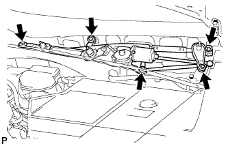
- Torque:
- 7.0 N*m{ 71 kgf*cm , 62 in.*lbf }
Connect the connector.
| 22. INSTALL COWL TOP VENTILATOR LOUVER SUB-ASSEMBLY |
| 23. INSTALL FRONT WIPER ARM AND BLADE ASSEMBLY RH |
Operate the front wiper, and stop the front wiper motor at the automatic stop position.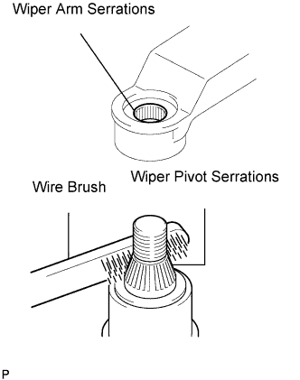
Clean the wiper arm serrations.
Clean the wiper pivot serrations with a wire brush (when reinstalling).
Install the front wiper arm and blade assembly LH with the nut at the position as shown in the illustration.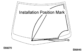
- Torque:
- 24 N*m{ 245 kgf*cm , 18 ft.*lbf }
- HINT:
- Hold the arm hinge by hand to fasten the nut.
| 24. INSTALL FRONT WIPER ARM AND BLADE ASSEMBLY LH |
Clean the wiper arm serrations.
Clean the wiper pivot serrations with a wire brush (when reinstalling).
Install the front wiper arm and blade assembly RH with the 2 nuts at the position as shown in the illustration.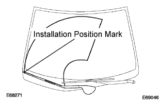
- Torque:
- 24 N*m{ 245 kgf*cm , 18 ft.*lbf }
- HINT:
- Hold the arm hinge by hand to fasten the nut.
Operate the front wipers while spraying water or washer fluid on the windshield.
Make sure that the wipers function properly and there is no interference with the vehicle body.
| 25. INSTALL ENGINE ROOM COVER SIDE |
Install the 5 clips and engine room cover side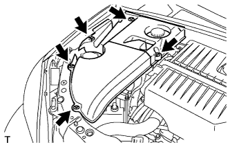
| 26. INSTALL ENGINE ROOM SIDE LH COVER |
Fit the clips and install the engine room side LH cover.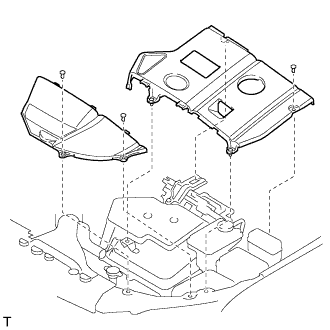
| 27. PERFORM INITIALIZATION |