Skid Control Buzzer Circuit
Circuit diagnosis
DESCRIPTION
The skid control buzzer sounds while the accumulator pressure is abnormally low or an abnormality causing low fluid pressure occurs, and then the VSC is activated.WIRING DIAGRAM
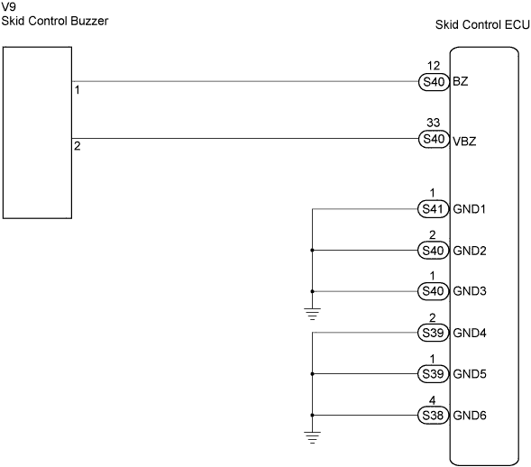

INSPECTION PROCEDURE
- NOTICE:
- When replacing the skid control ECU, perform initialization of linear solenoid valve and calibration (Click here).
| 1. PERFORM ACTIVE TEST BY INTELLIGENT TESTER (SKID CONTROL BUZZER) |

Connect the intelligent tester to the DLC3.
Turn the ignition switch on and turn the intelligent tester main switch on.
Select ACTIVE TEST mode on the intelligent tester.
ABS / VSC / TRAC: Item (Display)
Vehicle Condition/Test Details
Diagnostic Note
BUZZER
Turns skid control buzzer ON/OFF
Buzzer can be heard
Check that the buzzer sounds/stops when turning the skid control buzzer on/off using the intelligent tester.
- Result:
Condition
Proceed To
Buzzer sounds/stops
A
Buzzer does not sound or sounds constantly
B
- HINT:
- If troubleshooting has been carried out according to the PROBLEM SYMPTOMS TABLE, refer back to the table and proceed to the next step (Click here).
|
|
||||

| B | |
 |
| 2. INSPECT SKID CONTROL BUZZER (POWER SOURCE TERMINAL) |
Disconnect the skid control buzzer connector.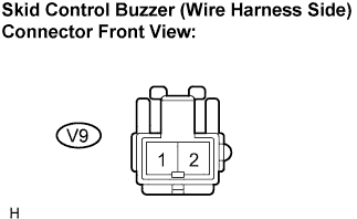
Turn the ignition switch on.
Measure the voltage according to the value(s) in the table below.
- Voltage:
Tester Connection
Condition
Specified Condition
V9-2 - Body ground
Ignition switch on
10 to 14 V
|
|
||||
| OK | |
|
| 3. INSPECT SKID CONTROL BUZZER |
Disconnect the skid control buzzer connector.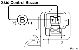
Apply battery negative voltage to terminal 1, and battery positive voltage to terminal 2 of the skid control buzzer, and then check that the buzzer sounds.
- OK:
- Skid control buzzer sounds.
|
|
||||
| OK | |
|
| 4. CHECK HARNESS AND CONNECTOR (BETWEEN SKID CONTROL ECU AND SKID CONTROL BUZZER) |
Disconnect the skid control buzzer connector and the skid control ECU connector.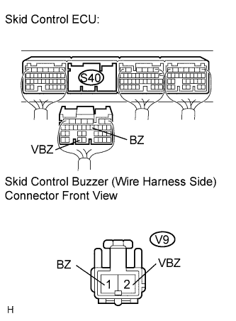
Measure the resistance according to the value(s) in the table below.
- Resistance:
Tester Connection
Specified Condition
S40-33 (VBZ) - V9-2 (VBZ)
Below 1 Ω
S40-12 (BZ) - V9-1 (BZ)
Below 1 Ω
Measure the resistance according to the value(s) in the table below.
- Resistance:
Tester Connection
Specified Condition
S40-33 (VBZ) - Body ground
10 kΩ or higher
S40-12 (BZ) - Body ground
10 kΩ or higher
|
|
||||
| OK | |
|
| 5. INSPECT SKID CONTROL ECU (GND TERMINAL) |
Measure the resistance according to the value(s) in the table below.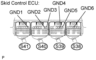
- Resistance:
Tester Connection
Specified Condition
S41-1 (GND1) - Body ground
Below 1 Ω
S40-2 (GND2) - Body ground
Below 1 Ω
S40-1 (GND3) - Body ground
Below 1 Ω
S39-2 (GND4) - Body ground
Below 1 Ω
S39-1 (GND5) - Body ground
Below 1 Ω
S38-4 (GND6) - Body ground
Below 1 Ω
|
|
||||
| OK | ||
 |
||
| ||