Open in One Side of CAN Sub Bus Line
Circuit diagnosis
DESCRIPTION
If 2 or more ECUs and/or sensors do not appear on the intelligent tester 'Communication Bus Check' screen, one side of the CAN sub-bus lines may be open. (One side of the CAN-H [sub-bus line] and CAN-L [sub-bus line] of the ECU and or sensor is open.)| Symptom |
Suspected Area |
| 2 or more ECUs and/or sensors do not appear on the intelligent tester "Communication Bus Check" screen. |
|
WIRING DIAGRAM
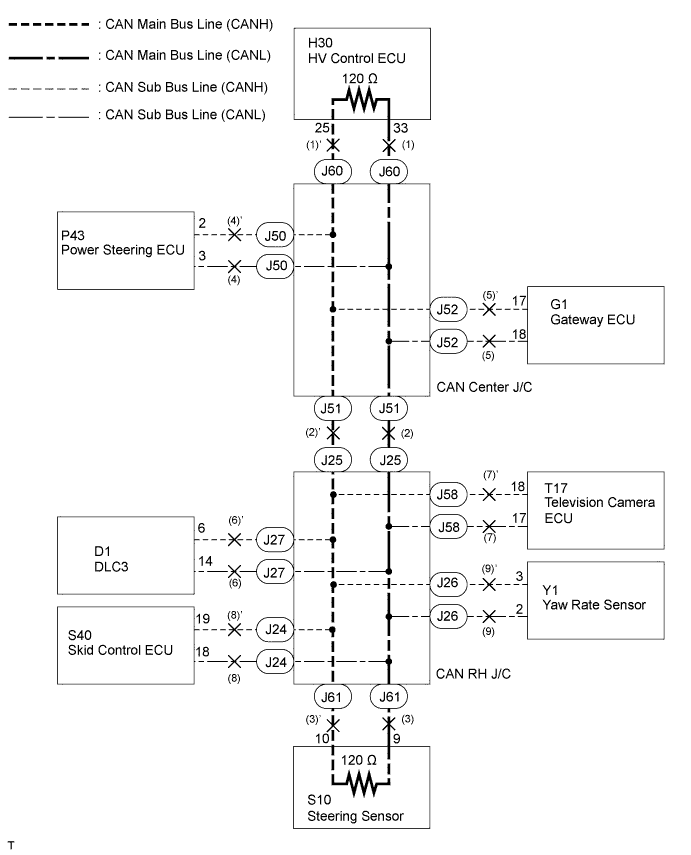

INSPECTION PROCEDURE
- HINT:
- Perform the following inspections for the ECUs (sensors) that are not displayed on the intelligent tester first. If a malfunction is still not able to be identified, perform the following inspections for all other ECUs (sensors) connected to the CAN communication system.
- The basic inspection procedures that can be used for all related ECUs in common are shown below.
"ECU A" represents the following: HV control ECU, steering sensor, yaw rate sensor, skid control ECU, network gateway ECU, television camera ECU, power steering ECU.
- Perform the following inspections for the ECUs (sensors) that are not displayed on the intelligent tester first. If a malfunction is still not able to be identified, perform the following inspections for all other ECUs (sensors) connected to the CAN communication system.
| 1. CHECK FOR AN OPEN IN ONE SIDE OF THE CAN SUB BUS LINE |

Disconnect the connector with terminals CANH and CANL of the ECU A (SENSORS).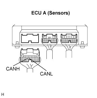
Select "Check the ECU connected to CAN BUS "on the intelligent tester.
- Result:
Result
Proceed to
ECUs only are not displayed on the intelligent tester.
A
- Several ECUs and sensors are not displayed on the intelligent tester.
- If the displayed ECUs and sensors are only those relating to the 'ENGINE' and 'HV', proceed to 'A'.
B
- Several ECUs and sensors are not displayed on the intelligent tester.
|
|
||||

| A | |
 |
| 2. CHECK FOR AN OPEN IN ONE SIDE OF THE CAN SUB BUS LINE |
Measure the resistance according to the value(s) in the table below.
- Standard Resistance:
ECU (Sensor)
Condition
Specified Value
HV control ECU
Disconnect the negative auxiliary battery cable
108 to 132 Ω
Steering sensor
Disconnect the negative auxiliary battery cable
108 to 132 Ω
Others
Disconnect the negative auxiliary battery cable
54 to 69 Ω
|
|
||||
| OK | ||
 |
||
| ||