IG Power Source Circuit
Circuit diagnosis
DESCRIPTION
The troubleshooting procedure for a situation in which no DTCs are output but the P/S warning light is always on is specified here. The P/S warning light remains on when there is an open in the IG circuit inputting power source voltage to the power steering ECU assembly.WIRING DIAGRAM
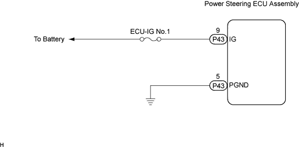

INSPECTION PROCEDURE
| 1. CHECK HARNESS AND CONNECTOR |

Check the indication condition of the P/S warning light while by wiggling the power steering ECU assembly connector and wire harness up and down, and then right and left.
- OK:
- P/S warning light indication condition does not change.
|
|
||||

| OK | |
 |
| 2. INSPECT CAN COMMUNICATION SYSTEM |
Using the intelligent tester, check for DTCs and confirm that there are no problems in the CAN communication system.
- OK:
- DTCs are not output.
|
|
||||
| OK | |
|
| 3. INSPECT MULTIPLEX COMMUNICATION SYSTEM (BEAN) |
Using the intelligent tester, check for DTCs and confirm that there are no problems in the multiplex communication system (BEAN).
- OK:
- DTCs are not output.
|
|
||||
| OK | |
|
| 4. INSPECT FUSE (ECU-IG No.1) |
Remove the ECU-IG No.1 fuse from the instrument panel J/B LH.
Check for continuity of the ECU-IG No.1 fuse.
- OK:
- Continuity
|
|
||||
| OK | |
|
| 5. INSPECT POWER STEERING ECU ASSEMBLY |
Disconnect the P43 connector from the power steering ECU assembly.
Measure the voltage according to the value(s) in the table below.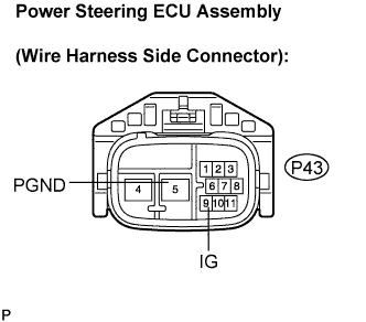
- Voltage:
Tester connection
(Symbols)
Condition
Specified condition
P43-9 (IG) -P43-5 (PGND)
Ignition switch on
10 to 14 V
|
|
||||

| NG | |
|
| 6. CHECK HARNESS AND CONNECTOR (BETWEEN POWER STEERING ECU ASSEMBLY AND BODY GROUND) |
Measure the resistance according to the value(s) in the table below.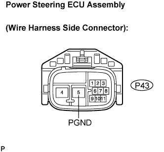
- Resistance:
Tester connection
(Symbols)
Condition
Specified condition
P43-5 (PGND) - Body ground
Always
Below 1 Ω
|
|
||||
| OK | ||
 |
||
| ||
| 7. REPLACE POWER STEERING ECU ASSEMBLY |
Replace the power steering ECU assembly (Click here).
- NOTICE:
- After replacing the power steering ECU assembly, initialize the rotation angle sensor value and calibrate the torque sensor zero point (Click here).
| NEXT | |
|
| 8. CHECK P/S WARNING LIGHT |
Check the P/S warning light status on the combination meter.
- Standard:
- The P/S warning light is off.
|
|
||||
| NG | ||
|
||
| ||