P0A05-776
Diagnostic trouble codes
DESCRIPTION
Refer to the circuit description of DTC P0A02-719 (Click here)| DTC No. |
INFO Code |
DTC Detection Condition |
Trouble Area |
| P0A05 |
776 |
Water pump malfunction |
|
WIRING DIAGRAM
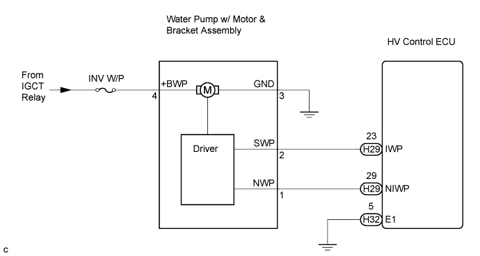

INSPECTION PROCEDURE
| 1. PERFORM ACTIVE TEST BY INTELLIGENT TESTER (WATER PUMP) |

Connect the intelligent tester to the DLC3.
Turn the ignition switch to the ON position.
Select the following menu items: Powertrain / Hybrid Control / Active Test / Active Water Pump.
During the water pump active test, check operation of the water pump.
- OK:
- There are ripples in the reservoir tank coolant.
- HINT:
- The water pump is also activated in the READY-on state.
|
|
||||

| OK | |
 |
| 2. INSPECT HYBRID VEHICLE CONTROL ECU |
Connect the intelligent tester to the DLC3.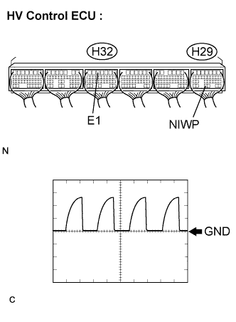
Put the vehicle into the READY-on state.
Select the following menu items: Powertrain / Hybrid Control / Active Test / Active Water Pump.
During the water pump active test, check for pulse signals according to the table below.
Item
Contents
Terminal
NIWP (H29-29) - E1 (H32-5)
Equipment Setting
5 V/DIV, 2 ms/DIV
Condition
During WATER PUMP active test
- OK:
- The waveform appears as shown in the illustration.
|
|
||||

| NG | |
|
| 3. CHECK HARNESS AND CONNECTOR (HV CONTROL ECU - WATER PUMP) |
Turn the ignition switch off.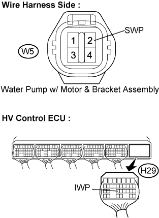
Disconnect the H29 connector from the HV control ECU.
Disconnect the W5 water pump connector.
Measure the resistance according to the value(s) in the table below.
- Standard Resistance (Check for open):
Tester Connection
Specified Condition
IWP (H29-23) - SWP (W5-2)
Below 1 Ω
|
|
||||
| OK | |
|
| 4. INSPECT WATER PUMP W/ MOTOR & BRACKET ASSEMBLY |
Disconnect the W5 water pump connector.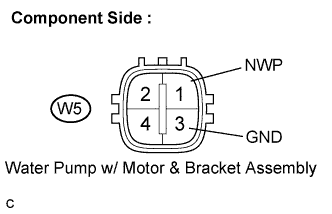
Measure the resistance according to the value(s) in the table below.
- Standard Resistance:
Tester Connection
Specified Condition
NWP (W5-1) - GND (W5-3)
1 MΩ or higher
|
|
||||
| OK | ||
 |
||
| ||
| 5. CHECK HARNESS AND CONNECTOR (WATER PUMP) |
Turn the ignition switch off.
Disconnect the W5 water pump w/ motor & bracket assembly connector.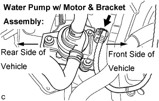
Measure the voltage according to the value(s) in the table below.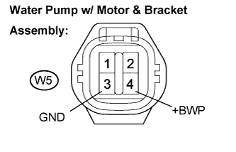
- Standard Voltage:
Tester Connection
Specified Condition
+BWP (W5-4) - GND (W5-3)
10 to 14 V
|
|
||||
| OK | |
|
| 6. CHECK COOLANT HOSE |
Check if the hoses of the cooling system are not bent or clogged.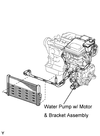
- OK:
- The hoses of the cooling system are not bent or clogged.
|
|
||||
| OK | |
|
| 7. CHECK HARNESS AND CONNECTOR (HV CONTROL ECU - WATER PUMP) |
Turn the ignition switch off.
Disconnect the H29 connector from the HV control ECU.
Disconnect the W5 water pump w/ motor & bracket assembly connector.
Measure the resistance according to the value(s) in the table below.
- Standard Resistance:
Tester Connection
Specified Condition
IWP (H29-23) - SWP (W5-2)
Below 1 Ω
|
|
||||
| OK | |
|
| 8. INSPECT HYBRID VEHICLE CONTROL ECU |
Connect the HV control ECU connector and water pump w/ motor & bracket assembly connector.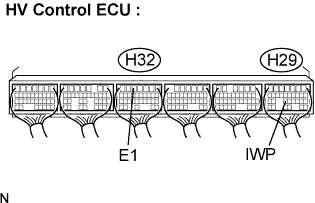
Turn the ignition switch to the ON position.
Measure the voltage according to the value(s) in the table below.
- Standard Voltage:
Tester Connection
Specified Condition
IWP (H29-23) - E1 (H32-5)
Below 1 V
|
|
||||
| NG | |
|
| 9. INSPECT WATER PUMP W/ MOTOR & BRACKET ASSEMBLY (SWP TERMINAL VOLTAGE) |
Disconnect the H29 connector from the HV control ECU.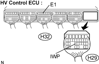
Turn the ignition switch to the ON position.
Measure the voltage according to the value(s) in the table below.
- Standard Voltage:
Tester Connection
Specified Condition
IWP (H29-23) - E1 (H32-5)
10 to 14 V
|
|
||||
| OK | ||
|
||
| ||
| 10. INSPECT HYBRID VEHICLE CONTROL ECU |
Put the vehicle into the READY-on state.
Measure the voltage according to the value(s) in the table below.
- Standard Voltage:
Tester Connection
Specified Condition
IWP (H29-23) - E1 (H32-5)
10 to 14 V
|
|
||||
| NG | ||
|
||
| ||