P0A09-265
Diagnostic trouble codes
DESCRIPTION
The DC/DC converter converts the DC 288 V of the HV battery into DC 12 V in order to supply power to areas such as the vehicle's lighting, audio and ECU systems. In addition, it charges the auxiliary battery.A transistor bridge circuit initially converts' DC 288 V into alternating current, and a transformer lowers its voltage. Then, it is rectified and smoothed (into DC) and converted into DC 12 V.
The DC/DC converter controls the output voltage in order to keep a constant voltage at the terminals of the auxiliary battery.
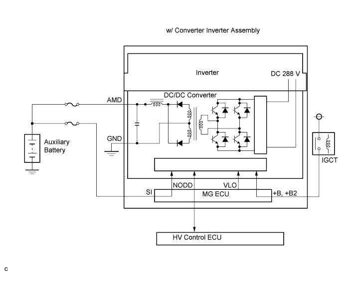

The HV control ECU uses the NODD signal line to transmit a stop command to the DC/DC converter and receive signals indicating the normal or abnormal conditions of the 12 V charging system.
If the vehicle is being driven with an inoperative DC/DC converter, the voltage of the auxiliary battery will drop, which will prevent the continued operation of the vehicle. Therefore, the HV control ECU monitors the operation of the DC/DC converter and alerts the driver if it detects a malfunction.
| DTC No. |
INF Code |
DTC Detection Condition |
Trouble Area |
| P0A09 |
265 |
Open or GND short in NODD signal circuit of DC/DC converter |
|
| P0A10 |
263 |
+B short in NODD signal circuit of DC/DC converter |
|
WIRING DIAGRAM
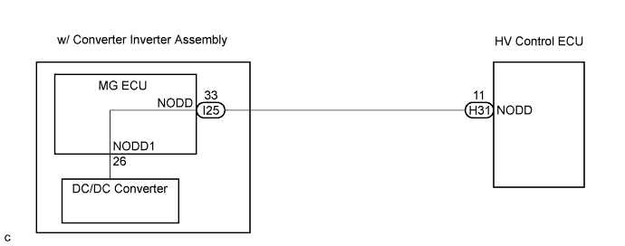
INSPECTION PROCEDURE
- CAUTION:
- Before inspecting the high-voltage system, take safety precautions to prevent electrical shocks, such as wearing insulated gloves and removing the service plug grip. After removing the service plug grip, put it in your pocket to prevent other technicians from reconnecting it while you are working on the high-voltage system.
- After disconnecting the service plug grip, wait for at least 5 minutes before touching any of the high-voltage connectors or terminals.
- Before inspecting the high-voltage system, take safety precautions to prevent electrical shocks, such as wearing insulated gloves and removing the service plug grip. After removing the service plug grip, put it in your pocket to prevent other technicians from reconnecting it while you are working on the high-voltage system.
- HINT:
- At least 5 minutes is required to discharge the high-voltage capacitor inside the w/ converter inverter assembly.
| 1. CHECK CONNECTION CONDITION OF MG ECU CONNECTOR (LOOSENESS AND POOR CONTACT) |

- CAUTION:
- Be sure to wear insulated gloves.
Turn the ignition switch off and remove the service plug grip. (Click here)
- NOTICE:
- Do not put the vehicle into the READY-on state with the service plug grip removed as this may cause a malfunction.
Remove the inverter cover. (Click here)
- NOTICE:
- Wrap the interlock round terminal for the inverter cover with vinyl tape to prevent it from shorting to ground.
- Prevent water in the reservoir tank from entering the inverter.
Removing the inverter cover causes the MG ECU board to be exposed. Therefore, temporarily install the inverter cover for each area to be inspected.
- Wrap the interlock round terminal for the inverter cover with vinyl tape to prevent it from shorting to ground.
Check the connections of the MG ECU connectors.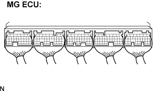
- OK:
- Connectors are connected securely and there is no poor connection.
|
|
||||

| OK | |
 |
| 2. CHECK HARNESS AND CONNECTOR (HV CONTROL ECU - MG ECU) |
- CAUTION:
- Be sure to wear insulated gloves.
Check that the service plug grip is removed.
Disconnect the H31 connector from the HV control ECU.
Disconnect the I25 connector from the MG ECU.
Measure the voltage according to the value(s) in the table below when the ignition switch is in the ON position.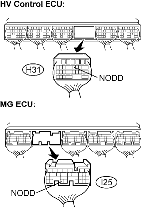
- NOTICE:
- Turning the ignition switch to the ON position with the MG ECU connectors disconnected causes other DTCs to be stored. Clear the DTCs after performing the inspection.
- Standard Voltage:
Tester Connection
Specified Condition
NODD (H31-11) - Body ground
Below 1 V
Turn the ignition switch off.
Measure the resistance according to the value(s) in the table below.
- Standard Resistance (Check for open):
Tester Connection
Specified Condition
NODD (H31-11) - NODD (I25-33)
Below 1 Ω
- Standard Resistance (Check for short):
Tester Connection
Specified Condition
NODD (H31-11) or NODD (I25-33) - Body ground
10 kΩ or more
|
|
||||
| OK | ||
 |
||
| ||