C1252/52
Diagnostic trouble codes
DESCRIPTION
The skid control ECU detects decreases in the accumulator pressure according to the data from the accumulator pressure sensor, and then starts and stops the pump motor by operating the motor relay.The skid control ECU usually drives the motor relay 1 for ECB control, and the motor relay 2 for ABS control.
If either is malfunctioning, the will other substitute.
| DTC No. |
INF Code |
DTC Detecting Condition |
Trouble Area |
| C1252/52 |
130 |
Motor relay is ON for at least 5 min. |
|
| C1253/53 |
132 |
Motor relay 1 coil (monitor) is energized for at least 1 sec. when main relay 1 monitor (BS1) is 9.5 V or more and motor relay 1 is off. |
|
| C1253/53 |
133 |
Motor relay 1 coil (monitor) is not energized for at least 1 sec. when main relay 1 monitor (BS1) is 9.5 V or more and motor relay 1 is on. |
|
| C1253/53 |
134 |
MTT input is 3.5 V or less for at least 0.2 sec. when main relay 1 monitor (BS1) is 9.5 V or more and motor relay 1 is on. |
|
| C1253/53 |
136 |
Motor relay 2 coil (monitor) is energized for at least 1 sec. when main relay 2 monitor (BS2) is 9.5 V or more and motor relay 2 is off. |
|
| C1253/53 |
137 |
Motor relay 2 coil (monitor) is not energized for at least 1 sec. (0.2 sec. during initial check) when main rely 2 monitor (BS2) is 9.5 V or more and motor relay 2 is on. |
|
| C1253/53 |
138 |
MTT input is 3.5 V or less for at least 1 sec. (0.2 sec. during initial check) when main relay 1 monitor (BS1) is 9.5 V or more and motor relay 2 is on. |
|
| C1253/53 |
140 |
MTT input is 3.5 V or more for at least 2 sec. when motor relay 1 and 2 are off. |
|
WIRING DIAGRAM
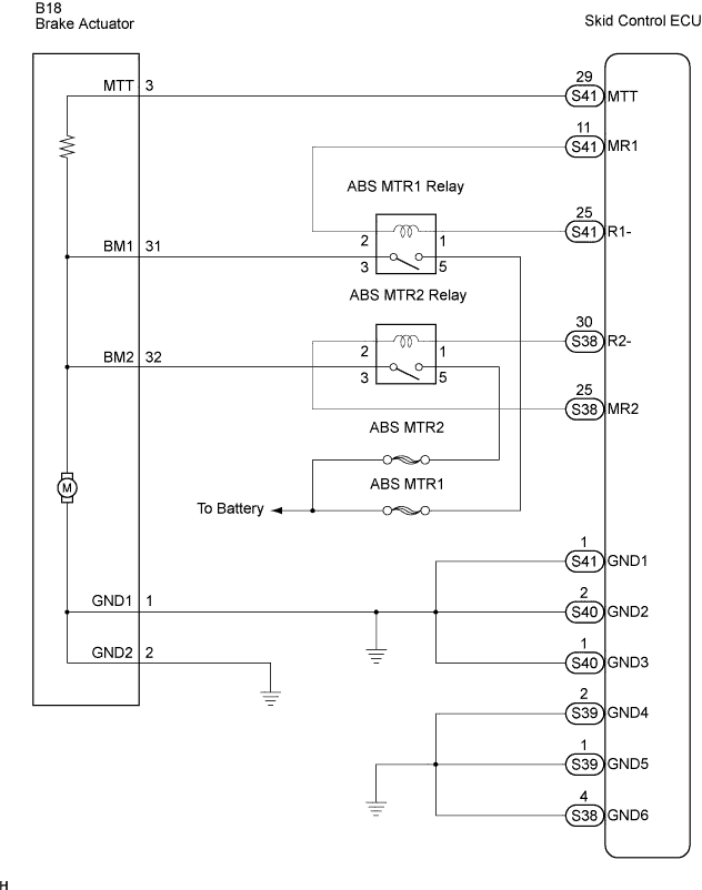

INSPECTION PROCEDURE
- NOTICE:
- When replacing the skid control ECU, perform initialization of linear solenoid valve and calibration (Click here).
| 1. PERFORM ACTIVE TEST BY INTELLIGENT TESTER (ECB MOTOR RELAY) |

Connect the intelligent tester to the DLC3.
Turn the ignition switch on.
Select the ACTIVE TEST mode on the intelligent tester.
Check the operating sound of the ABS motor individually when operating it with the intelligent tester.
ABS / VSC / TRAC: Item
Measurement Item /
Range (Display)
Normal Condition
ECB Motor Relay
Turns ABS MTR1 Relay ON/OFF
Operating of solenoid
(clicking sound) can be heard
ECB Motor Relay 2
Turns ABS MTR 2 Relay ON/OFF
Operating of solenoid
(clicking sound) can be heard
- OK:
- The operating sound of the ABS motor should be heard.
|
|
||||

| OK | |
 |
| Go to step 3 |
| 2. INSPECT FUSE (ABS MTR1 AND ABS MTR2 FUSES) |
Remove the ABS MTR1 and ABS MTR2 fuses from the engine room R/B No.4.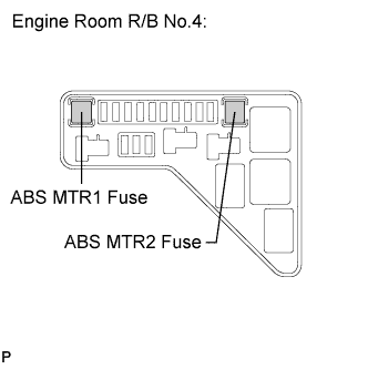
Measure the resistance according to the value(s) in the table below.
- Resistance:
Fuse
Specified Condition
ABS MTR1
Below 1 Ω (Continuity)
ABS MTR2
Below 1 Ω (Continuity)
|
|
||||

| OK | |
|
| Go to step 2 |
| 3. INSPECT BRAKE ACTUATOR ASSEMBLY |
Disconnect the brake actuator assembly connector.
Measure the resistance according to the value(s) in the table below.
- Resistance:
Tester Connection
Specified Condition
32 (BM2) - 1 (GND1)
Below 10 Ω
31 (BM1) - 1 (GND1)
Below 10 Ω
32 (BM2) - 31 (BM1)
Below 1 Ω
1 (GND1) - 2 (GND2)
Below 1 Ω
32 (BM2) - 3 (MTT)
About 33 Ω
31 (BM1) - 3 (MTT)
About 33 Ω
|
|
||||
| OK | |
|
| 4. CHECK HARNESS AND CONNECTOR (BETWEEN SKID CONTROL ECU AND BRAKE ACTUATOR ASSEMBLY) |
Disconnect the skid control ECU connector and brake actuator assembly connector.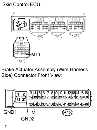
Measure the resistance according to the value(s) in the table below.
- Resistance:
Tester Connection
Specified Condition
S41-29 (MTT) - B18-3 (MTT)
Below 1 Ω
B18-1 (GND1) - Body ground
Below 1 Ω
B18-2 (GND2) - Body ground
Below 1 Ω
|
|
||||
| OK | |
|
| 5. READ VALUE OF INTELLIGENT TESTER (ACCUMULATOR PRESSURE SENSOR) |
Connect the intelligent tester to the DLC3.
Turn the ignition switch on.
Select the DTA LIST mode on the intelligent tester.
ABS / VSC / TRAC: Item
Measurement Item /
Range (Display)
Normal Condition
Accumulator Sensor
Accumulator pressure sensor /
min.: 0 V, max.: 5 V
Specified value: 3.2 to 4.0 V
Depress the brake pedal 4 or 5 times to operate the pump motor, and check the output value on the intelligent tester with the motor stopped (not braking).
- OK:
- Accumulator (ACC) pressure sensor voltage does not drop.
|
|
||||
| OK | ||
 |
||
| ||
| 6. INSPECT ABS MOTOR RELAY |
Remove the ABS MTR1 relay and ABS MTR 2 relay.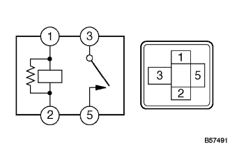
Measure the resistance according to the value(s) in the table below.
- Resistance:
Tester Connection
Connection
Specified Resistance
3 - 5
Always
10 kΩ or higher
(No continuity)
3 - 5
Apply B+ between terminals 1 and 2
Below 1 Ω
|
|
||||
| OK | |
|
| 7. CHECK HARNESS AND CONNECTOR (BETWEEN ENGINE ROOM R/B NO.4 AND BATTERY) |
Remove the ABS MTR1 relay and ABS MTR 2 relay.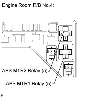
Measure the voltage according to the value(s) in the table below.
- Voltage:
Tester Connection
Specified Condition
ABS MTR1 Relay (5) - Body ground
10 to 14 V
ABS MTR 2 Relay (5) - Body ground
10 to 14 V
|
|
||||
| OK | |
|
| 8. CHECK HARNESS AND CONNECTOR (BETWEEN ENGINE ROOM R/B NO.4 AND BREAK ACTUATOR ASSEMBLY) |
Disconnect the brake actuator assembly connector.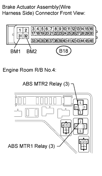
Remove the ABS MTR1 relay and ABS MTR 2 relay.
Measure the resistance according to the value(s) in the table below.
- Resistance:
Tester Connection
Specified Condition
B18-32 (BM2) - ABS MTR 2 Relay (3)
Below 1 Ω
B18-31 (BM1) - ABS MTR1 Relay (3)
Below 1 Ω
Measure the resistance according to the value(s) in the table below.
- Resistance:
Tester Connection
Specified Condition
A2-1 (BM2) - Body ground
10 kΩ or higher
A2-2 (BM1) - Body ground
10 kΩ or higher
|
|
||||
| OK | |
|
| 9. CHECK HARNESS AND CONNECTOR (BETWEEN ENGINE ROOM R/B NO.4 AND SKID CONTROL ECU) |
Disconnect the skid control ECU connector.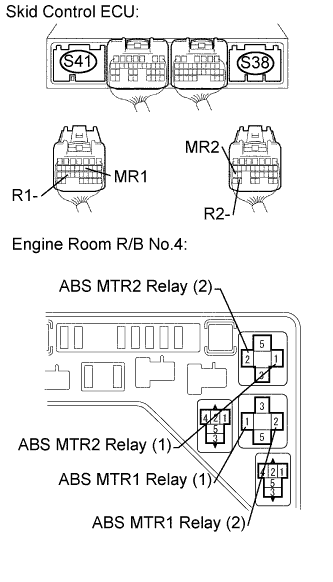
Remove the ABS MTR1 relay and ABS MTR2 relay.
Measure the resistance according to the value(s) in the table below.
- Resistance:
Tester Connection
Specified Condition
S41-11 (MR1) - ABS MTR1 Relay (2)
Below 1 Ω
S41-25 (R1-) - ABS MTR1 Relay (1)
Below 1 Ω
S38-25 (MR2) - ABS MTR 2 Relay (2)
Below 1 Ω
S38-30 (R2-) - ABS MTR 2 Relay (1)
Below 1 Ω
Measure the resistance according to the value(s) in the table below.
- Resistance:
Tester Connection
Specified Condition
S41-11 (MR1) - Body ground
10 kΩ or higher
S41-25 (R1-) - Body ground
10 kΩ or higher
S38-25 (MR2) - Body ground
10 kΩ or higher
S38-30 (R2-) - Body ground
10 kΩ or higher
|
|
||||
| OK | ||
|
||
| ||