P0A1D-139
Diagnostic trouble codes
DESCRIPTION
| DTC No. |
INF Code |
DTC Detection Condition |
Trouble Area |
| P0A1D |
139 |
Relay activation IC error |
|
MONITOR DESCRIPTION
The HV control ECU performs diagnostic monitoring to verify proper operation of vehicle systems. The inside of the HV control ECU is checked by one of these monitors for a bad integrated circuit which actuates a relay. If the HV control ECU detects a malfunction, it will illuminate the MIL and set a DTC.WIRING DIAGRAM
Refer to the wiring diagram of P3110-223. (Click here)INSPECTION PROCEDURE
| 1. CHECK HARNESS AND CONNECTOR (HV CONTROL ECU - IGCT RELAY) |

Disconnect the H34 connector from the HV control ECU.
Remove the IGCT relay from the R/B No.2.
Measure the voltage according to the value(s) in the table below when the ignition switch is in the ON position.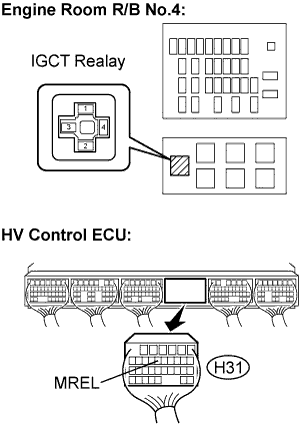

- NOTICE:
- Turning the ignition switch to the ON position with the HV control ECU connectors disconnected causes other DTCs to be stored. Clear the DTCs after performing the inspection.
- Standard voltage:
Tester Connection
Specified Condition
MREL (H31-12) - Body ground
Below 1 V
|
|
||||

| OK | |
 |
| 2. INSPECT IGCT RELAY |
Remove the IGCT relay from the engine room R/B No.4.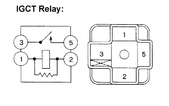
Measure the resistance according to the value(s) in the table below.
- Standard Resistance:
Tester Connection
Specified Condition
3 - 5
10 kΩ or more
3 - 5
Below 1 Ω
(when battery voltage is applied to terminals 1 and 2)
|
|
||||
| OK | ||
 |
||
| ||