P0A2C-247
Diagnostic trouble codes
DESCRIPTION
The resistance of the thermistor built into the motor temperature sensor changes in accordance with changes in Motor temperature. The lower the Motor temperature, the higher the termistor resistance. Conversely, the higher the temperature, the lower the resistance.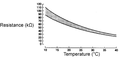

| DTC No. |
INF Code |
DTC Detection Condition |
Trouble Area |
| P0A2C |
247 |
GND short in motor temperature sensor circuit |
|
| P0A2D |
249 |
Open or +B short in motor temperature sensor circuit |
|
- HINT:
- After confirming that DTC P0A2C-247 or P0A2D-249 is output, use the intelligent tester to check "MOTOR 2 TEMP" in the HV system ECU data list.
Displayed Temperature
Malfunction
-50°C
Open or +B short circuit
205°C
GND short
WIRING DIAGRAM
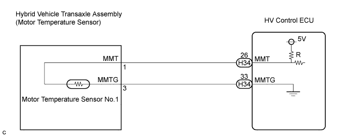
INSPECTION PROCEDURE
| 1. CHECK CONNECTION CONDITION OF HYBRID VEHICLE CONTROL ECU CONNECTOR (LOOSENESS AND POOR CONTACT) |

Check the connections of all HV control ECU connectors.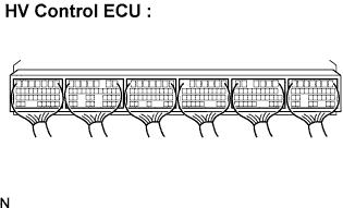
- OK:
- Connectors are connected securely and there is no poor connection.
|
|
||||

| OK | |
 |
| 2. INSPECT HYBRID VEHICLE CONTROL ECU |
Turn the ignition switch to the ON position. Measure the voltage according to the value(s) in the table below.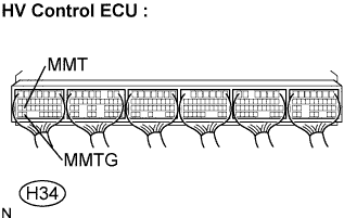
- Result:
Tester Connection
Voltage
Proceed to
MMT (H34-26) - MMTG (H34-33)
Approximately 0 or 5 V
A
9 to 14V
B
|
|
||||

| B | |
|
| 3. CHECK HARNESS AND CONNECTOR (+B SHORT) |
Disconnect the H34 connector from the HV control ECU.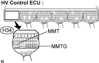
Turn the ignition switch to the ON position.
Measure the voltage according to the value(s) in the table below.
- Result::
Tester Connection
Voltage
Proceed to
MMT (H34-26) - MMTG (H34-33)
Approximately 0 V
A
9 to 14V
B
- NOTICE:
- Turning the ignition switch to the ON position with the HV control ECU connectors disconnected causes other DTCs to be stored. Clear the DTCs after performing the inspection.
|
|
||||
| B | |
|
| 4. CHECK HARNESS AND CONNECTOR (+B SHORT) |
Disconnect the H34 connector from the HV control ECU.
Disconnect the M8 motor temperature sensor connector.
Turn the ignition switch to the ON position.
Measure the voltage according to the value(s) in the table below.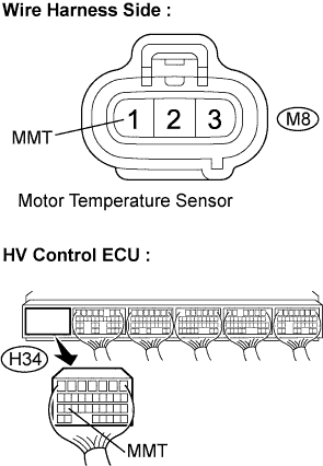
- Standard Voltage:
Tester Connection
Specified Condition
MMT (M8-1) or MMT (H34-26) - Body ground
Approximately 0 V
- NOTICE:
- Turning the ignition switch to the ON position with the HV control ECU connectors disconnected causes other DTCs to be stored. Clear the DTCs after performing the inspection.
- HINT:
- The motor temperature sensor is not available as a single product. If it requires replacement, replace the HV transaxle assembly.
|
|
||||
| OK | ||
 |
||
| ||
| 5. INSPECT MOTOR TEMPERATURE SENSOR |
Disconnect the H34 connector from the HV control ECU.
Measure the resistance according to the value(s) in the table below.
- Standard Resistance:
Tester Connection
Resistance
Temperature
MMT (H34-26) - MMTG (H34-33)
142.6 k to 184.1 kΩ
0°C
44.2 k to 54.4 kΩ
25°C
16.2 k to 19.1 kΩ
50°C
3.3 k to 3.5 kΩ
100°C
Measure the resistance according to the value(s) in the table below.
- Standard Resistance:
Tester Connection
Specified Condition
MMT (H34-26) or MMTG (H34-33) - Body ground
10 kΩ or higher
|
|
||||
| NG | |
|
| 6. CHECK HARNESS AND CONNECTOR (HV CONTROL ECU - MOTOR TEMPERATURE SENSOR) |
Disconnect the H34 connector from the HV control ECU.
Disconnect the M8 motor temperature sensor connector.
Measure the resistance according to the value(s) in the table below.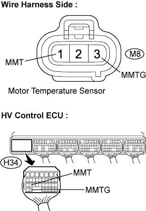
- Standard Resistance:
Tester Connection
Specified Condition
MMT (H34-26) - MMT (M8-1)
Below 1 Ω
MMTG (H34-33) - MMTG (M8-3)
Below 1 Ω
- Standard Resistance:
Tester Connection
Specified Condition
MMT (H34-26) or MMTG (H34-33) - Body ground
10 kΩ or higher
- HINT:
- The motor temperature sensor is not available as a single product. If it requires replacement, replace the HV transaxle assembly.
|
|
||||
| OK | ||
|
||
| ||