P0A3F-243
Diagnostic trouble codes
DESCRIPTION
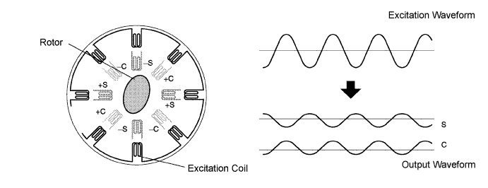
A resolver is a sensor that detects the position of the magnetic poles, which are indispensable for ensuring highly efficient control of the Motor and Generator.The resolver stator contains an excitation coil and 2 detection coils. The gap between the stator and rotor changes as the rotor turns because the rotor is oval shaped. An alternating current with a predetermined frequency flows through the excitation coil, and detection coils S and C output alternating currents in accordance with the sensor rotor position.
The MG ECU detects the absolute position of the rotor according to the phases of detection coils S and C and the height of their waveforms. Furthermore, the CPU calculates the amount of change in the position within a predetermined length of time, in order to use the resolver as a speed sensor.
The MG ECU monitors signals output from the Motor resolver and detects a malfunction.

| DTC No. |
INF Code |
DTC Detection Condition |
Trouble Area |
| P0A3F |
243 |
Interphase short in motor resolver circuit |
|
| P0A40 |
500 |
Motor resolver output is out of normal range |
|
| P0A41 |
245 |
Open or short in motor resolver circuit |
|
MONITOR DESCRIPTION
The MG ECU monitors the motor resolver output signal. If the MG ECU detects output signals that are out of the normal range or specification, it will conclude that there is a malfunction of the motor resolver. The HV control ECU will illuminate the MIL and set a DTC.WIRING DIAGRAM
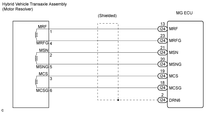
INSPECTION PROCEDURE
- CAUTION:
- Before inspecting the high-voltage system, take safety precautions to prevent electrical shocks, such as wearing insulated gloves and removing the service plug grip. After removing the service plug grip, put it in your pocket to prevent other technicians from reconnecting it while you are working on the high-voltage system.
- After disconnecting the service plug grip, wait for at least 5 minutes before touching any of the high-voltage connectors or terminals.
- Before inspecting the high-voltage system, take safety precautions to prevent electrical shocks, such as wearing insulated gloves and removing the service plug grip. After removing the service plug grip, put it in your pocket to prevent other technicians from reconnecting it while you are working on the high-voltage system.
- NOTICE:
- Check the output DTCs again after the repair has been completed. If P0A78-286, P0A7A-324, or P0A79-696 is output, replace the w/ converter inverter assembly.
- HINT:
- At least 5 minutes is required to discharge the high-voltage capacitor inside the w/ converter inverter assembly.
- If the problem symptom cannot be reproduced, performing the driving test on a road on which the vehicle tends to vibrate will make it easier to reproduce the symptom.
- If INF code 243 is output, there may be an interphase short in the Motor resolver circuit due to an intrusion of water into the resolver. Therefore, if the problem symptom cannot be reproduced, replace the HV transaxle assembly last.
- At least 5 minutes is required to discharge the high-voltage capacitor inside the w/ converter inverter assembly.
| 1. CHECK CONNECTION CONDITION OF MG ECU CONNECTOR (LOOSENESS AND POOR CONTACT) |

- CAUTION:
- Be sure to wear insulated gloves.
Turn the ignition switch off and remove the service plug grip. (Click here)
- NOTICE:
- Do not put the vehicle into the READY-on state with the service plug grip removed as this may cause a malfunction.
Remove the inverter cover. (Click here)
- NOTICE:
- Wrap the interlock round terminal for the inverter cover with vinyl tape to prevent it from shorting to ground.
- Prevent water in the reservoir tank from entering the inverter.
- Removing the inverter cover causes the MG ECU board to be exposed. Therefore, temporarily install the inverter cover for each area to be inspected.
- Wrap the interlock round terminal for the inverter cover with vinyl tape to prevent it from shorting to ground.
Check the connections of the MG ECU connectors.
- OK:
- Connectors are connected securely and there is no poor connection.
|
|
||||

| OK | |
 |
| 2. INSPECT MOTOR RESOLVER |
- CAUTION:
- Be sure to wear insulated gloves.
Disconnect the I24 connector from the MG ECU.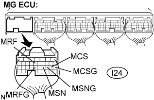
Measure the voltage according to the value(s) in the table below when the ignition switch is in the ON position.
- Standard Voltage:
Tester Connection
Specified Condition
MRF (I24-13) - Body ground
Below 1 V
MRFG (I24-23) - Body ground
Below 1 V
MSN (I24-21) - Body ground
Below 1 V
MSNG (I24-20) - Body ground
Below 1 V
MCS (I24-19) - Body ground
Below 1 V
MCSG (I24-18) - Body ground
Below 1 V
- NOTICE:
- Turning the ignition switch to the ON position with the MG ECU connectors disconnected causes other DTCs to be stored. Clear the DTCs after performing the inspection.
Turn the ignition switch off.
Measure the resistance according to the value(s) in the table below.
- Standard Resistance (Check for open):
Tester Connection
Specified Condition
MRF (I24-13) - MRFG (I24-23)
7.65 to 10.2 Ω
MSN (I24-21) - MSNG (I24-20)
12.6 to 16.8 Ω
MCS (I24-19) - MCSG (I24-18)
12.6 to 16.8 Ω
- Standard Resistance (Check for short):
Tester Connection
Specified Condition
MRF (I24-13) or MRFG (I24-23) - Body ground
10 kΩ or higher
MSN (I24-21) or MSNG (I24-20) - Body ground
10 kΩ or higher
MCS (I24-19) or MCSG (I24-18) - Body ground
10 kΩ or higher
|
|
||||
| OK | |
|
| 3. CHECK CONNECTION CONDITION OF MOTOR RESOLVER CONNECTOR (LOOSENESS AND POOR CONTACT) |
Check the connection of the motor resolver connector.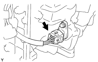
- OK:
- Connector is connected securely and there is no poor connection.
|
|
||||
| OK | |
|
| 4. INSPECT MOTOR RESOLVER |
Disconnect the M7 motor resolver connector.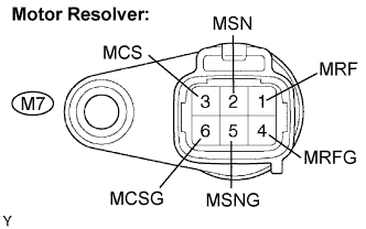
Measure the resistance according to the value(s) in the table below.
- Standard Resistance:
Tester Connection
Specified Condition
MRF (M7-1) - MRFG (M7-4)
7.65 to 10.2 Ω
MSN (M7-2) - MSNG (M7-5)
12.6 to 16.8 Ω
MCS (M7-3) - MCSG (M7-6)
12.6 to 16.8 Ω
Using a megohmmeter, measure the insulation resistance according to the value(s) in the table below.
- Standard Resistance:
Tester Connection
Specified Condition
MRF (M7-1) - MSN (M7-2)
10 MΩ or higher
MRF (M7-1) - MCS (M7-3)
10 MΩ or higher
MSN (M7-2) - MCS (M7-3)
10 MΩ or higher
MRFG (M7-4) - MSNG (M7-5)
10 MΩ or higher
MRFG (M7-4) - MCSG(M7-6)
10 MΩ or higher
MSNG (M7-5) - MCSG (M7-6)
10 MΩ or higher
Each terminal listed above - Transaxle housing
10 MΩ or higher
|
|
||||
| OK | ||
 |
||
| ||