TERMINALS OF ECU
System information
| AIR CONDITIONING AMPLIFIER |
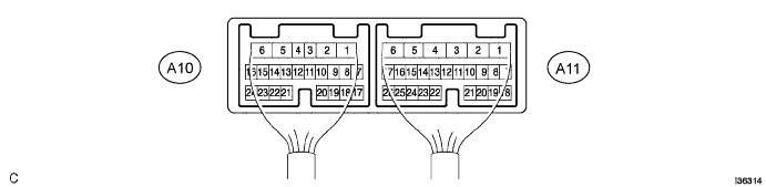

- HINT:
- Check from the rear of the connector with it connected to the air conditioning amplifier assembly.
| Terminal No. (Symbols) |
Wiring color |
Terminal Description |
Condition |
Specification |
| A11-1 (IG+) - A11-6 (GND) |
Y - W-B |
Ignition switch signal |
Ignition switch: LOCK or ACC |
Below 1 V |
| A11-1 (IG+) - A11-6 (GND) |
Y - W-B |
Ignition switch signal |
Ignition switch: ON |
10 to 14 V |
| A11-2 (B) - A11-6 (GND) |
SB - W-B |
Back-up power source |
Always |
10 to 14 V |
| A11-3 (MPX+) - A11-6 (GND) |
BR - W-B |
Terminal for BEAN |
Engine idling after engine warmed up |
Pulse generation |
| A11-4 (MPX-) - A11-6 (GND) |
GR - W-B |
Terminal for BEAN |
Engine idling after engine warmed up |
Pulse generation |
| A11-5 (WIP) - A11-6 (GND) |
W - W-B |
Wiper operation signal |
Ignition switch: ON Wiper stop position |
Below 1 V |
| A11-5 (WIP) - A11-6 (GND) |
W - W-B |
Wiper operation signal |
Ignition switch: ON Other than wiper stop position (Operating) |
10 to 14 V |
| A11-6 (GND) - Body ground |
W-B - Body ground |
Ground for main power supply |
Always |
Below 1 V |
| A11-8 (FDEF) - A11-6 (GND) |
B - W-B |
Front deicer switch signal |
Ignition switch: ON Front deicer switch: OFF |
10 to 14 V |
| A11-8 (FDEF) - A11-6 (GND) |
B - W-B |
Front deicer switch signal |
Ignition switch: ON Front deicer switch: ON |
Below 1 V |
| A11-9 (BLW) - A11-6 (GND) |
L - W-B |
Blower switch signal |
Ignition switch: ON Blower switch: ON |
Pulse generation (See waveform 1) |
| A11-10 (TSD) - A11-6 (GND) |
R - W-B*1
Y - W-B*2 |
Light sensor (Driver side) |
Ignition switch: ON Light sensor covered with a cloth |
Below 0.8 V |
| A11-10 (TSD) - A11-6 (GND) |
R - W-B*1
Y - W-B*2 |
Light sensor (Driver side) |
Ignition switch: ON Light sensor exposed to electric light |
0.8 to 4.3 V |
| A11-11 (TSP) - A11-6 (GND) |
Y - W-B*1
R - W-B*2 |
Light sensor (Passenger side) |
Ignition switch: ON Light sensor covered with a cloth |
Below 0.8 V |
| A11-11 (TSP) - A11-6 (GND) |
Y - W-B*1
R - W-B*2 |
Light sensor (Passenger side) |
Ignition switch: ON Light sensor exposed to electric light |
0.8 to 4.3 V |
| A11-18 (HR) - A11-6 (GND) |
W - W-B |
Blower switch signal |
Ignition switch: ON Blower switch: OFF |
10 to 14 V |
| A11-18 (HR) - A11-6 (GND) |
W - W-B |
Blower switch signal |
Ignition switch: ON Blower switch: ON |
Below 1 V |
| A11-18 (HR) - A11-6 (GND) |
W - W-B |
Blower switch signal |
Ignition switch: OFF Blower switch: OFF |
Below 1 V |
| A11-19 (DFG) - A11-6 (GND) |
G - W-B |
Rear defogger switch signal |
Ignition switch: ON Rear defogger switch: OFF |
10 to 14 V |
| A11-19 (DFG) - A11-6 (GND) |
G - W-B |
Rear defogger switch signal |
Rear defogger switch: ON |
Below 1 V |
| A11-21 (TR) - A11-6 (GND) |
O - V |
Room temperature sensor signal |
Ignition switch: ON Cabin temperature: 25°C (77°F) |
1.8 to 2.2 V |
| A11-21 (TR) - A11-6 (GND) |
O - V |
Room temperature sensor signal |
Ignition switch: ON Cabin temperature: 40°C (105°F) |
1.3 to 1.7 V |
| A11-22 (RH) - A11-6 (GND) |
SB - W-B |
Power supply for humidity sensor |
Ignition switch: ON |
4.5 to 5.5 V |
| A11-24 (SSR+) - A11-6 (GND) |
P - W-B |
Humidity sensor signal |
Ignition switch: ON Cabin humidity: 40% |
2.0 V |
| A11-24 (SSR+) - A11-6 (GND) |
P - W-B |
Humidity sensor signal |
Ignition switch: ON Cabin humidity: 60% |
2.5 V |
| A11-26 (SG-5) - Body ground |
V - Body ground |
Ground for room temperature sensor |
Always |
Below 1 V |
| A10-3 (AIR) - A7-6 (GND) |
R - W-B |
Recirculation/Fresh switch signal |
Ignition switch: ON Recirculation/Fresh switch: FRESH |
Below 1 V |
| A10-3 (AIR) - A11-6 (GND) |
R - W-B |
Recirculation/Fresh switch signal |
Ignition switch: ON Recirculation/Fresh switch: RECIRCULATION |
10 to 14 V |
| A10-4 (AIF) - A11-6 (GND) |
G - W-B |
Recirculation/Fresh switch signal |
Ignition switch: ON Recirculation/Fresh switch: RECIRCULATION |
Below 1 V |
| A10-4 (AIF) - A11-6 (GND) |
G - W-B |
Recirculation/Fresh switch signal |
Ignition switch: ON Recirculation/Fresh switch: FRESH |
10 to 14 V |
| A10-5 (AOF) - A11-6 (GND) |
W - W-B |
Mode switch signal |
Ignition switch: ON Mode switch: DEF |
Below 1 V |
| A10-5 (AOF) - A11-6 (GND) |
W - W-B |
Mode switch signal |
Ignition switch: ON Mode switch: FACE |
10 to 14 V |
| A10-6 (AOD) - A11-6 (GND) |
B - W-B |
Mode switch signal |
Ignition switch: ON Mode switch: FACE |
Below 1 V |
| A10-6 (AOD) - A11-6 (GND) |
B - W-B |
Mode switch signal |
Ignition switch: ON Mode switch: DEF |
10 to 14 V |
| A10-7 (TPI) - A10-17 (SG-4) |
BR - L |
Recirculation/Fresh switch signal |
Ignition switch: ON Recirculation/Fresh switch: RECIRCULATION |
Above 4 V |
| A10-7 (TPI) - A10-17 (SG-4) |
BR - L |
Recirculation/Fresh switch signal |
Ignition switch: ON Recirculation/Fresh switch: FRESH |
Below 1 V |
| A10-8 (TPO) - A10-18 (SG-3) |
Y - R |
Mode switch signal |
Ignition switch: ON Mode switch: FACE |
Below 1 V |
| A10-8 (TPO) - A10-18 (SG-3) |
Y - R |
Mode switch signal |
Ignition switch: ON Mode switch: DEF |
Above 4 V |
| A10-9 (TPD) - A10-20 (SG-1) |
P - BR |
Temperature switch signal (Driver side) |
Ignition switch: ON Temperature switch: MAX.COOL |
Above 4 V |
| A10-9 (TPD) - A10-20 (SG-1) |
P - BR |
Temperature switch signal (Driver side) |
Ignition switch: ON Temperature switch: MAX.HOT |
Below 1 V |
| A10-10 (TPP) - A10-19 (SG-2) |
V - W |
Temperature switch signal (Passenger side) |
Ignition switch: ON Temperature switch: MAX.COOL |
Above 4 V |
| A10-10 (TPP) - A10-19 (SG-2) |
V - W |
Temperature switch signal (Passenger side) |
Ignition switch: ON Temperature switch: MAX.HOT |
Below 1 V |
| A10-11 (SG) - Body ground |
L - Body ground |
Ground for evaporator temperature sensor |
Always |
Below 1 V |
| A10-12 (TE) - A10-11 (SG) |
GR - L |
Evaporator temperature sensor signal |
Ignition switch: ON Evaporator temperature: 0°C (32°F) |
2.2 to 2.6 V |
| A10-12 (TE) - A10-11 (SG) |
GR - L |
Evaporator temperature sensor signal |
Ignition switch: ON Evaporator temperature: 15°C (59°F) |
1.3 to 1.7 V |
| A10-13 (S5-4) - A10-17 (SG-4) |
B - L |
Power supply for air inlet damper position sensor |
Ignition switch: ON |
4.5 to 5.5 V |
| A10-14 (AMDC) - A11-6 (GND) |
LG - W-B |
Temperature switch (Driver side) |
Ignition switch: ON Temperature switch: MAX.HOT |
Below 1 V |
| A10-14 (AMDC) - A11-6 (GND) |
LG - W-B |
Temperature switch (Driver side) |
Ignition switch: ON Temperature switch: MAX.COOL |
10 to 14 V |
| A10-15 (AMDH) - A11-6 (GND) |
O - W-B |
Temperature switch (Driver side) |
Ignition switch: ON Temperature switch: MAX.COOL |
Below 1 V |
| A10-15 (AMDH) - A11-6 (GND) |
O - W-B |
Temperature switch (Driver side) |
Ignition switch: ON Temperature switch: MAX.HOT |
10 to 14 V |
| A10-16 (AMPC) - A11-6 (GND) |
R - W-B |
Temperature switch (Passenger side) |
Ignition switch: ON Temperature switch: MAX.HOT |
Below 1 V |
| A10-16 (AMPC) - A11-6 (GND) |
R - W-B |
Temperature switch (Passenger side) |
Ignition switch: ON Temperature switch: MAX.COOL |
10 to 14 V |
| A10-17 (SG-4) - Body ground |
L - Body ground |
Ground for air inlet damper position sensor |
Always |
Below 1 V |
| A10-18 (SG-3) - Body ground |
R - Body ground |
Ground for air outlet damper position sensor |
Always |
Below 1 V |
| A10-19 (SG-2) - Body ground |
W - Body ground |
Ground for air mix damper position sensor (Passenger side) |
Always |
Below 1 V |
| A10-20 (SG-1) - Body ground |
BR - W-B |
Ground for air mix damper position sensor (Driver side) |
Always |
Below 1 V |
| A10-21 (S5-3) - A10-18 (SG-3) |
V - R |
Power supply for air outlet damper position sensor |
Ignition switch: ON |
4.5 to 5.5 V |
| A10-22 (S5-2) - A10-19 (SG-2) |
L - W |
Power supply for air mix damper position sensor (Passenger side) |
Ignition switch: ON |
4.5 to 5.5 V |
| A10-23 (S5-1) - A10-20 (SG-1) |
GR - BR |
Power supply for air mix damper position sensor (Driver side) |
Ignition switch: ON |
4.5 to 5.5 V |
| A10-24 (AMPH) - A11-6 (GND) |
G - W-B |
Temperature switch (Passenger side) |
Ignition switch: ON Temperature switch: MAX.COOL |
Below 1 V |
| A10-24 (AMPH) - A11-6 (GND) |
G - W-B |
Temperature switch (Passenger side) |
Ignition switch: ON Temperature switch: MAX.HOT |
10 to 14 V |
- *1: LHD
- *2: RHD
Waveform 1:
Measure the waveform between terminal BLW (A10-9) of the A/C amplifier assembly and body ground.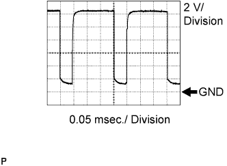
- OK:
- Waveform appears as shown in the illustration.
- HINT:
- Waveform cycle varies with the blower level.
| HYBRID VEHICLE CONTROL ECU |
- HINT:
- Check from the rear of the connector with it connected to the hybrid vehicle control ECU.
| Terminal No. (Symbols) |
Wiring color |
Terminal Description |
Condition |
Specification |
| H31-13 (PR2) - H31-20 (HP) |
L-W - L-B |
A/C pressure switch signal |
Ignition switch: ON A/C switch: ON Refrigerant pressure: 0.196 to 3.14 Mpa (32 kgf/cm2) |
Below 1 V |
| H31-13 (PR2) - H31-20 (HP) |
L-W - L-B |
A/C pressure switch signal |
Ignition switch: ON A/C switch: ON Refrigerant pressure: Below 0.196 Mpa (2.0 kgf/cm2) or more than 3.14 Mpa (32 kgf/cm2) |
10 to 14 V |
| H31-19 (TAM) - H34-28 (E2) |
Y - BR |
Ambient temperature sensor signal |
Ignition switch: ON at 25°C (77°F) |
1.8 to 2.2 V |
| H31-19 (TAM) - H34-28 (E2) |
Y - BR |
Ambient temperature sensor signal |
Ignition switch: ON at 40°C (104°F) |
1.2 to 1.6 V |
| H33-14 (CLK) - Body ground |
G - Body ground |
Compressor operation signal |
Ignition switch: ON |
Pulse generation (See waveform A) |
| H33-15 (ITE) - Body ground |
W - Body ground |
Compressor operation signal |
Ignition switch: ON |
Pulse generation (See waveform B) |
| H33-16 (ETI) - Body ground |
Y - Body ground |
Compressor operation signal |
Ignition switch: ON |
Pulse generation (See waveform C) |
| H33-18 (STB) - Body ground |
B - body ground |
Compressor operation signal |
Ignition switch: ON |
10 to 14 V |
| H33-18 (STB) - Body ground |
B - Body ground |
Compressor operation signal |
Ignition switch: OFF |
Below 1 V |
| H31-4 (WP) - Body ground |
L - Body ground |
Water pump operation signal |
Not operate the heater water pump |
10 to 14 V |
| H31-4 (WP) - Body ground |
L - Body ground |
Water pump operation signal |
Operate the heater water pump |
Below 1 V |
Waveform A: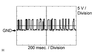
Measure the waveform between terminal CLK (H33-14) of the hybrid vehicle control ECU and body ground.
- OK:
- Waveform appears as shown in the illustration.
- HINT:
- Waveform cycle varies with the communication contents.
Waveform B: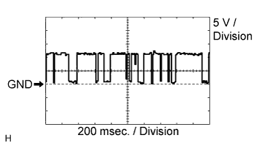
Measure the waveform between terminal ITE (H33-15) of the hybrid vehicle control ECU and body ground.
- OK:
- Waveform appears as shown in the illustration.
- HINT:
- Waveform cycle varies with the communication contents.
Waveform C: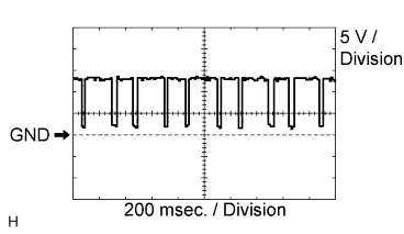
Measure the waveform between terminal ETI (H33-16) of the hybrid vehicle control ECU and body ground.
- OK:
- Waveform appears as shown in the illustration.
- HINT:
- Waveform cycle varies with the communication contents.
| INTEGRATION CONTROL & PANEL ASSEMBLY |

- HINT:
- Check from the rear of the connector with it connected to the integration control & panel assembly.
| Terminal No. (Symbols) |
Wiring color |
Terminal Description |
Condition |
Specification |
| C4-1 (+B) - C4-7 (GND) |
O - W-B |
Main power supply |
Always |
10 to 14 V |
| C4-2 (ACC) - C4-7 (GND) |
GR - W-B |
ACC power supply |
Ignition switch: ACC |
10 to 14 V |
| C4-4 (LP) - C4-7 (GND) |
P - W-B |
Security indicator |
Security: Operate |
10 to 14 V |
| C4-5 (MPX+) - C4-7 (GND) |
L - W-B |
Terminal for BEAN |
Ignition switch: ON |
Pulse generation |
| C4-7 (GND) - Body ground |
W-B - Body ground |
Ground for power supply |
Always |
Below 1 V |
| C4-8 (ILL+) - C4-14 (ILL-) |
G - W |
Power supply for illumination |
Dimmer switch: OFF |
Below 1 V |
| C4-8 (ILL+) - C4-14 (ILL-) |
G - W |
Power supply for illumination |
Dimmer switch: TAIL or HEAD |
10 to 14 V |
| C4-9 (IG+) - C4-7 (GND) |
LG - W-B |
IG power supply |
Ignition switch: ON |
10 to 14 V |
| C4-11 (F) - C4-7 (GND) |
V - W-B |
Hazard switch |
Hazard switch: OFF |
10 to 14 V |
| C4-11 (F) - C4-7 (GND) |
V - W-B |
Hazard switch |
Hazard switch: ON |
Below 1 V |
| C4-12 (MPX-) - C4-7 (GND) |
R - W-B |
Terminal for BEAN |
Ignition switch: ON |
Pulse generation |
| C4-14 (ILL-) - Body ground |
W - Body ground |
Ground for illumination |
Always |
Below 1 V |
| MULTI DISPLAY ASSEMBLY |