B1423/23
Diagnostic trouble codes
DESCRIPTION
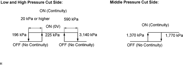

The A/C pressure switch to detect the refrigerant pressure is located in the sight glass side of the pipe on the high-pressure side. This DTC is output when the refrigerant pressure is either significantly low (below 196 kPa (2.0 kgf/cm2, 28 psi) or significantly high (over 3,140 kPa (32.0 kgf/cm2, 455 psi). Then the A/C pressure switch has built-in switches to detect high and low pressure and is turned off when either of them is determined to be detective. The A/C amplifier assembly continuously monitors the pressure switch signal after the ignition switch is turned on. It stops compressor control and outputs the DTC when it detects the signal indicating that the switch is turned off.
| DTC No. |
DTC Detecting Condition |
Trouble Area |
| B1423/23 |
|
|
WIRING DIAGRAM
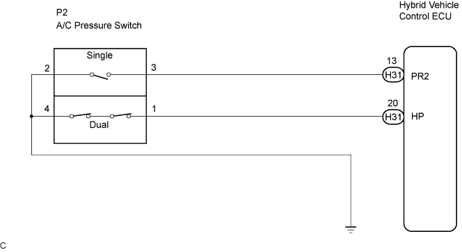
INSPECTION PROCEDURE
| 1. INSPECT REFRIGERANT PRESSURE |

Set the manifold gauge (Click here).
Read the manifold gauge pressure when the following conditions are established.
- Temperature at the air inlet with the switch set at RECIRCULATION is 30 to 35°C (86 to 95°F)
- Ignition switch is ON.
- Blower speed control switch is at "HI" position
- Temperature control dial is at "COOL" position
- Air conditioning switch is ON
- Doors are fully open
- Standard pressure:
- Pressure on high pressure side:
- 1.37 to 1.57 MPa (13.9 to 16.0 kgf/cm2, 198 to 228 psi)
- HINT:
- If the refrigerant pressure is below 196 kPa (2.0 kgf/cm2, 28 psi), the refrigerant amount in the air conditioning cycle may have decreased significantly for reasons such as a gas leakage.
- Temperature at the air inlet with the switch set at RECIRCULATION is 30 to 35°C (86 to 95°F)
|
|
||||

| OK | |
 |
| 2. CHECK AIR CONDITIONING OPERATION |
Disconnect the connector from the A/C pressure switch.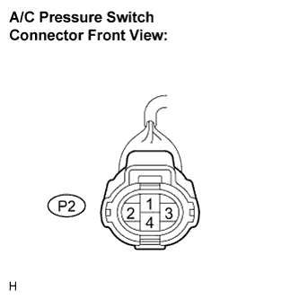
Connect the terminals 1 and 4 of the connector of the pressure switch on the vehicle wire harness side using a service wire.
Turn the ignition switch ON.
Turn the air conditioning switch ON and check that the compressor is operated.
Check that the compressor is not operated when terminals 1 and 4 are disconnected (that were connected in the prior step).
- OK:
- Terminals 1 and 4 connected: the compressor is operated
- Terminals 1 and 4 disconnected: the compressor is not operated
Check that the electrical fan is operated when terminals 2 and 3 are disconnected (that were connected in the prior step).
- OK:
- Terminals 2 and 3 connected: the electrical fan is operated
- Terminals 2 and 3 disconnected: the electrical fan is not operated
|
|
||||

| OK | ||
 |
||
| ||
| 3. CHECK HARNESS AND CONNECTOR (A/C PRESSURE SWITCH - HYBRID VEHICLE CONTROL ECU) |
Disconnect the connectors from the A/C pressure sensor and the hybrid vehicle control ECU.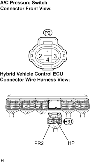
Measure the resistance according to the value(s) in the table below.
- Resistance:
Tester connection
(Symbols)
Condition
Specified condition
H31-13 (PR2) - P2-3
Always
Below 1 Ω
H31-20 (HP) - P2-1
Always
Below 1 Ω
H31-13 (PR2) - Body round
Always
10 kΩ or higher
H31-20 (HP) - Body ground
Always
10 kΩ or higher
P2-2 - Body ground
Always
Below 1 Ω
P2-4 - Body ground
Always
Below 1 Ω
- Result:
Result
Proceed to
NG
A
OK (Checking from the PROBLEM SYMPTOMS TABLE)
B
OK (Checking from the DTC)
C
|
|
||||
|
|
||||
| A | ||
|
||
| ||