B1433/33
Diagnostic trouble codes
DESCRIPTION
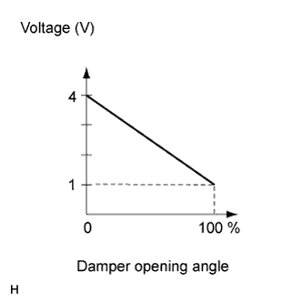

This sensor detects the position of the air outlet control servomotor and sends the appropriate signals to the A/C amplifier assembly. The position sensor is built in the air outlet control servomotor. The potentiometer's resistance changes as the air outlet control servomotor arm moves.
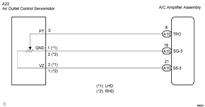
It outputs voltage (5 V) that is input to terminal 2 (VZ) and terminal 3 (PT) via the variable resistor, and then to the A/C amplifier assembly. The A/C amplifier assembly reads the arm position with the input voltage from the position sensor.
| DTC No. |
DTC Detecting Condition |
Trouble Area |
| B1433/33 |
Open or short in power source circuit in air outlet damper position sensor circuit. |
|
WIRING DIAGRAM
INSPECTION PROCEDURE
| 1. READ VALUE OF INTELLIGENT TESTER |

Connect the intelligent tester to the DLC3.
Turn the ignition switch ON and push the intelligent tester main switch on.
Select the items below in the DATA LIST, and read the displays on the intelligent tester.
| Item |
Measurement Item/Display (Range) |
Normal Condition |
Diagnostic Note |
| A/O DAMP POS |
Air outlet damper position / min.: -14% max.: 113.5% |
Damper is at "FACE": 0% Damper is at "FACE/FOOT": 33.5%*1, 23.5%*2 Damper is at "FOOT" (Manual): 53.5%*1, 56.5%*2 Damper is at "FOOT" (Auto): 53.5%:1, 56.5%*2 Damper is at "FACE/DEF": 73.5%*1, 76.5%*2 Damper is at "DEF": 100% |
Open in the circuit: 50.0% |
| A/O DAMP TARG |
Air outlet damper target position / min.: -14% max.: 113.5% |
- *1: LHD
- *2: RHD
- OK:
- The display is as specified in the normal condition.
- Result:
Result
Proceed to
NG
A
OK (Checking from the PROBLEM SYMPTOM TABLE)
B
OK (Checking from the DTC)
C
|
|
||||
|
|
||||

| A | |
 |
| 2. INSPECT AIR CONDITIONING AMPLIFIER ASSEMBLY |
Remove the A/C amplifier assembly with the connectors still connected.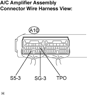
Measure the voltage according to the value(s) in the table below.
- Voltage:
Tester connection
(Symbols)
Condition
Specified condition
A10-8 (TPO) - A10-18 (SG-3)
Ignition switch ON
FACE position
3.97 to 4.03 V
A10-8 (TPO) - A10-18 (SG-3)
Ignition switch ON
DEF position
0.97 to 1.03 V
A10-21 (S5-3) - A10-18 (SG-3)
Ignition switch ON
4.5 to 5.5 V
A10-21 (S5-3) - A10-18 (SG-3)
Ignition switch OFF
Below 1 V
- HINT:
- As the air outlet control servomotor is moved from the "FACE" side to "DEF" side, the voltage decreases gradually without interruption.
- Result:
Result
Proceed to
NG
A
OK (Checking from the PROBLEM SYMPTOMS TABLE)
B
OK (Checking from the DTC)
C
|
|
||||
|
|
||||
| A | |
|
| 3. INSPECT AIR OUTLET CONTROL SERVOMOTOR |
Remove the air outlet control servomotor.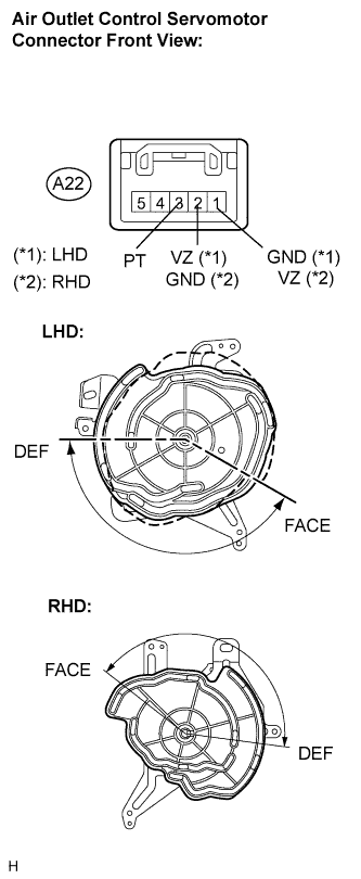
Disconnect the connector from the air outlet control servomotor.
Measure the resistance according to the value(s) in the table below.
- Resistance:
Tester connection
(Symbols)
Condition
Specified condition
A22-2 (VZ) - A22-1 (GND)*1
Always
4.2 to 7.8 kΩ
A22-1 (VZ) - A22-2 (GND)*2
Always
4.2 to 7.8 kΩ
- *1: LHD
- *2: RHD
Measure the resistance according to the value(s) in the table below.
- Resistance:
Tester connection
(Symbols)
Condition
Specified condition
A22-3 (PT) - A22-1 (GND)*1
DEF position
0.8 to 1.6 kΩ
A22-3 (PT) - A22-1 (GND)*1
FACE position
3.4 to 6.2 kΩ
A22-3 (PT) - A22-2 (GND)*2
DEF position
0.8 to 1.6 kΩ
A22-3 (PT) - A22-2 (GND)*2
FACE position
3.4 to 6.2 kΩ
- *1: LHD
- *2: RHD
As the air outlet control servomotor is moved from the "DEF" side to "FACE" side, the resistance decreases gradually without interruption.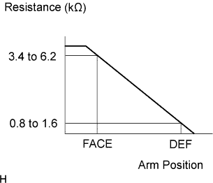
- HINT:
- For details regarding operation of the servomotor (Click here).
|
|
||||
| OK | |
|
| 4. CHECK HARNESS AND CONNECTOR (AIR OUTLET CONTROL SERVOMOTOR - A/C AMPLIFIER ASSEMBLY) |
Disconnect the connector from the A/C amplifier assembly.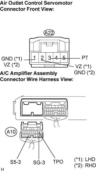
Measure the resistance according to the value(s) in the table below.
- Resistance:
Tester connection
(Symbols)
Condition
Specified condition
A10-8 (TPO) - A22-3 (PT)
Always
Below 1 Ω
A10-18 (SG-3) - A22-1 (GND)*1
Always
Below 1 Ω
A10-18 (SG-3) - A22-2 (GND)*2
Always
Below 1 Ω
A10-21 (S5-3) - A22-2 (VZ)*1
Always
Below 1 Ω
A10-21 (S5-3) - A22-1 (VZ)*2
Always
Below 1 Ω
A10-8 (TPO) - Body ground
Always
10 kΩ or higher
A10-18 (SG-3) - Body ground
Always
10 kΩ or higher
A10-21 (S5-3) - Body ground
Always
10 kΩ or higher
- *1: LHD
- *2: RHD
|
|
||||
| OK | ||
 |
||
| ||