B1442/42
Diagnostic trouble codes
DESCRIPTION
The air inlet control servomotor is controlled by the A/C amplifier assembly and moves the air inlet control servomotor to the desired position.The air inlet control servomotor switches between "RECIRCULATION" and "FRESH" by rotating the motor (normal, reverse) with electrical power from the A/C amplifier assembly. This controls intake air and switches "RECIRCULATION", "FRESH" and "HALF-RECIRCULATION".
| DTC No. |
DTC Detecting Condition |
Trouble Area |
| B1442/42 |
Air inlet damper position sensor value does not change even if air conditioning amplifier assembly operates air outlet damper control servomotor. |
|
WIRING DIAGRAM
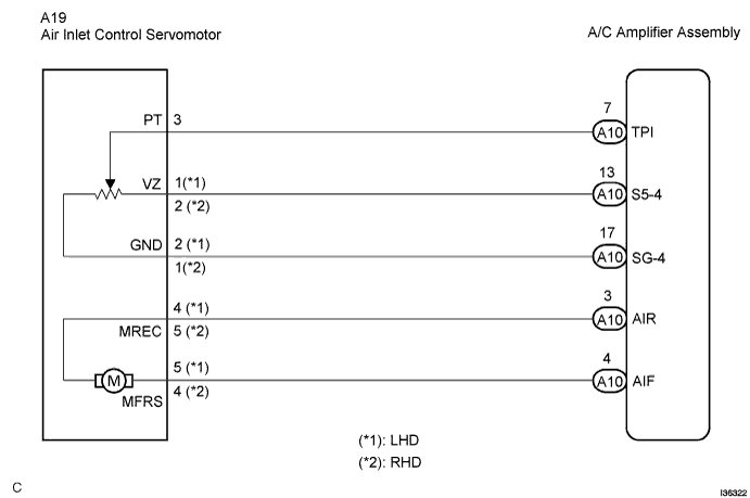

INSPECTION PROCEDURE
| 1. READ VALUE OF INTELLIGENT TESTER |

Connect the intelligent tester to the DLC3.
Turn the ignition switch ON and push the intelligent tester main switch on.
Select the item below in the DATA LIST, and read the display on the intelligent tester.
| Item |
Measurement Item/Display (Range) |
Normal Condition |
Diagnostic Note |
| A/I DAMP POS |
Air inlet damper position / min.: -14% max.: 113.5% |
Damper is at "RECIRCULATION": -9% Damper is at "HALF-RECIRCULATION": 35 to 75% Damper is at "FRESH": 109% |
Open in the circuit: 50.0% |
| A/I DAMP TARG |
Air inlet damper target position / min.: -14% max.: 113.5% |
- OK:
- When the target position is at the "RECIRCULATION" (-9%), the actual opening angle is 19.0% or less.
When the target position is at the "FRESH" (109%), the actual opening angle is 81.0% or more.
- Result:
Result
Proceed to
NG
A
OK (Checking from the PROBLEM SYMPTOMS TABLE)
B
OK (Checking from the DTC)
C
|
|
||||
|
|
||||

| A | |
 |
| 2. PERFORM ACTIVE TEST BY INTELLIGENT TESTER |
Remove the glove box and check the recirculation damper operation.
Connect the intelligent tester to the DLC3.
Turn the ignition switch ON and push the intelligent tester main switch on.
Select the item below in the ACTIVE TEST and then check that the damper operates.
ACTIVE TEST / AIR CONDITIONER Item
Test Details/Display
(Range)
Diagnostic Note
A/I DAMP-LINEAR
Air inlet damper position (linear) /min.: -14% max.: 113.5%
-
- OK:
- Lever turns from "RECIRCULATION" side to "FRESH" side smoothly.
Lever turns from "FRESH" side to "RECIRCULATION" side smoothly.
- Result:
Result
Proceed to
NG
A
OK (Checking from the PROBLEM SYMPTOMS TABLE)
B
OK (Checking from the DTC)
C
|
|
||||
|
|
||||
| A | |
|
| 3. PERFORM ACTUATOR CHECK |
Remove the glove box and check the recirculation damper operation.
Set the actuator check mode (Click here).
Press the UPDr switch in order and check the operation of recirculation damper.
| Display Code |
Recirculation damper position |
| 0 |
FRESH (109%) |
| 1 |
FRESH (109%) |
| 2 |
R/F (50%) |
| 3 |
RECIRCULATION (-9%) |
| 4 |
FRESH (109%) |
| 5 |
FRESH (109%) |
| 6 |
FRESH (109%) |
| 7 |
FRESH (109%) |
| 8 |
FRESH (109%) |
| 9 |
FRESH (109%) |
- OK:
- Recirculation damper position changes in accordance with each display code.
- Result:
Result
Proceed to
NG
A
OK (Checking from the PROBLEM SYMPTOMS TABLE)
B
OK (Checking from the DTC)
C
|
|
||||
|
|
||||
| A | |
|
| 4. INSPECT AIR INLET CONTROL SERVOMOTOR |
Remove the air inlet control servomotor.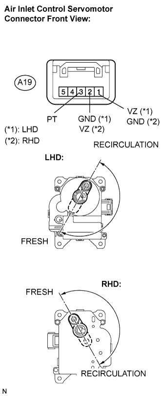
Disconnect the connector from the air inlet control servomotor.
Connect the positive (+) lead from the battery to terminal 5 and the negative (-) lead to terminal 4, then check that the lever turns to the "FRESH" position smoothly.
- OK:
- Lever turns to "FRESH" position smoothly.
Connect the positive (+) lead from the battery to terminal 4 and the negative (-) lead to terminal 5, then check that the lever turns to the "RECIRCULATION" position smoothly.
- OK:
- Lever turns to "RECIRCULATION" position smoothly.
|
|
||||
| OK | |
|
| 5. CHECK HARNESS AND CONNECTOR (AIR INLET CONTROL SERVOMOTOR - A/C AMPLIFIER ASSEMBLY) |
Disconnect the connector from the A/C amplifier assembly.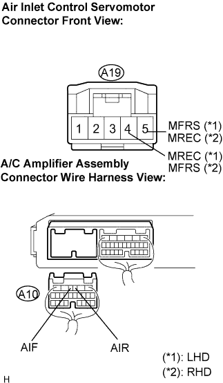
Measure the resistance according to the value(s) in the table below.
- Resistance:
Tester connection
(Symbols)
Condition
Specified condition
A10-3 (AIR) - A19-4 (MREC)*1
Always
Below 1 Ω
A10-3 (AIR) - A19-5 (MREC)*2
Always
Below 1 Ω
A10-4 (AIF) - A19-5 (MFRS)*1
Always
Below 1 Ω
A10-4 (AIF) - A19-4 (MFRS)*2
Always
Below 1 Ω
A10-3 (AIR) - Body ground
Always
10 kΩ or higher
A10-4 (AIF) - Body ground
Always
10 kΩ or higher
- (*1): LHD
- (*2): RHD
|
|
||||
| OK | ||
 |
||
| ||