B1473/73
Diagnostic trouble codes
DESCRIPTION
The inverter activation signal is sent to the w/ motor compressor assembly from the hybrid vehicle control ECU. Compressor control is stopped and the DTC is output if there is an open or short in the signal circuit.| DTC No. |
DTC Detecting Condition |
Trouble Area |
| B1473/73 |
Open or short in A/C inverter start-up signal system. |
|
WIRING DIAGRAM
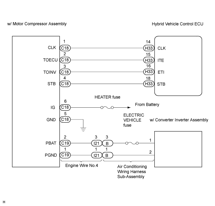

INSPECTION PROCEDURE
- NOTICE:
- If DTC B1473/73 and B1498/98 (inverter local communication problem) are output simultaneously, perform inspection for B1498/98 first by following the flow chart.
| 1. CHECK DIAGNOSTIC TROUBLE CODE |

Check if DTCs for the hybrid control system are output using the intelligent tester.
- OK:
- DTCs are not output in the hybrid control system.
|
|
||||

| OK | |
 |
| 2. CHECK HARNESS AND CONNECTOR (HYBRID VEHICLE CONTROL ECU - W/MOTOR COMPRESSOR ASSEMBLY) |
Disconnect the connectors from the hybrid vehicle control ECU and the w/ motor compressor assembly.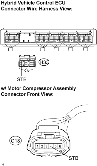
Measure the resistance according to the value(s) in the table below.
- Resistance:
Tester connection
(Symbols)
Condition
Specified condition
C18-4 (STB) - H33-18 (STB)
Always
Below 1 Ω
C18-4 (STB) - Body ground
Always
10 kΩ or higher
- CAUTION:
- Do not disconnect the connector on the high-voltage side.
|
|
||||
| OK | |
|
| 3. INSPECT W/MOTOR COMPRESSOR ASSEMBLY |
Reconnect the connector to the w/ motor compressor assembly.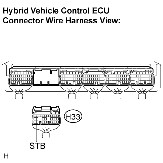
Measure the voltage according to the value(s) in the table below.
- Voltage:
Tester connection
(Symbols)
Condition
Specified condition
H33-18 (STB) - Body ground
Ignition switch ON
10 to 14 V
H33-18 (STB) - Body ground
Ignition switch OFF
Below 1 V
|
|
||||
| OK | ||
 |
||
| ||