B1498/98
Diagnostic trouble codes
DESCRIPTION
The hybrid vehicle control ECU and w/ motor compressor transmit information to one another via communication line. Compressor control is stopped and the DTC is output if communication information is cut off or abnormal information occurs.The DTC is also detected if high-voltage power supplied from the w/ converter inverter assembly to the compressor control circuit is shut off.
The output DTC is memorized as previous trouble.
- CAUTION:
- Wear electrically insulated gloves and pull out the service plug grip before inspection as procedures may require disconnecting high-voltage connectors. Be sure to carry the removed service plug grip because other workers may install it by mistake.
- Do not touch the high-voltage connectors or terminals for 5 minutes after the service plug grip is removed.
- Wear electrically insulated gloves and pull out the service plug grip before inspection as procedures may require disconnecting high-voltage connectors. Be sure to carry the removed service plug grip because other workers may install it by mistake.
| DTC No. |
Detection item |
Trouble Area |
| B1498/98 |
|
|
WIRING DIAGRAM
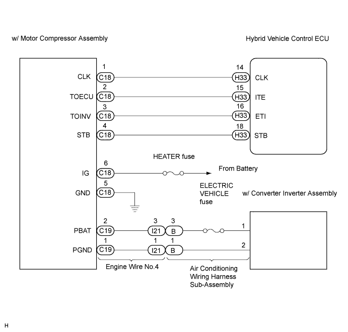

INSPECTION PROCEDURE
| 1. CHECK DIAGNOSTIC TROUBLE CODE |

Check if DTCs for the hybrid control system are output using the intelligent tester.
- Result:
Result
Proceed to
DTC is not output
A
DTC (P3108) is output
A
Except DTC (P3108) is output
B
|
|
||||

| A | |
 |
| 2. INSPECT HEATER FUSE |
Remove the HEATER fuse from instrument panel J/B.
Measure the resistance according to the value(s) in the table below.
- Resistance:
Tester Item
Condition
Specified condition
HEATER fuse
Always
Below 1 Ω
|
|
||||
| OK | |
|
| 3. CHECK HARNESS AND CONNECTOR (W/MOTOR COMPRESSOR ASSEMBLY - BODY GROUND) |
Disconnect the connector from the w/ motor compressor assembly.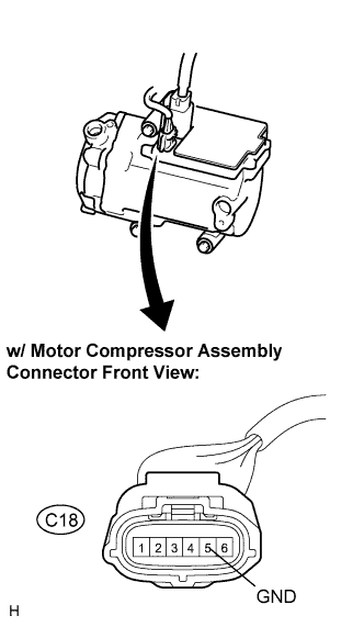
- CAUTION:
- Do not disconnect the connector on the high-voltage side.
Measure the resistance according to the value(s) in the table below.
- Resistance:
Tester connection
(Symbols)
Condition
Specified condition
C18-5 (GND) - Body ground
Always
Below 1 Ω
|
|
||||
| OK | |
|
| 4. CHECK HARNESS AND CONNECTOR (IG1 - GND) |
Turn the ignition switch ON.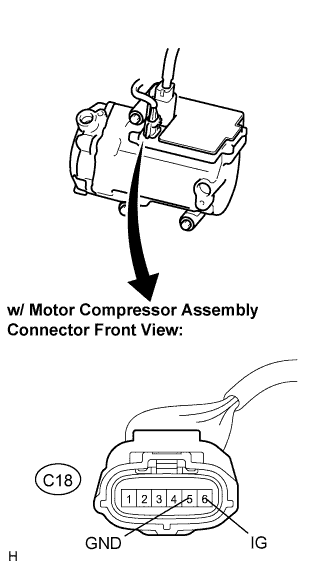
Measure the voltage according to the value(s) in the table below.
- Voltage:
Tester connection
(Symbols)
Condition
Specified condition
C18-6 (IG) - C18-5 (GND)
Ignition switch ON
10 to 14 V
C18-6 (IG) - C18-5 (GND)
Ignition switch OFF
Below 1 V
|
|
||||
| OK | |
|
| 5. CHECK HARNESS AND CONNECTOR (HYBRID VEHICLE CONTROL ECU - W/MOTOR COMPRESSOR ASSEMBLY) |
Disconnect the connector from the hybrid vehicle control ECU.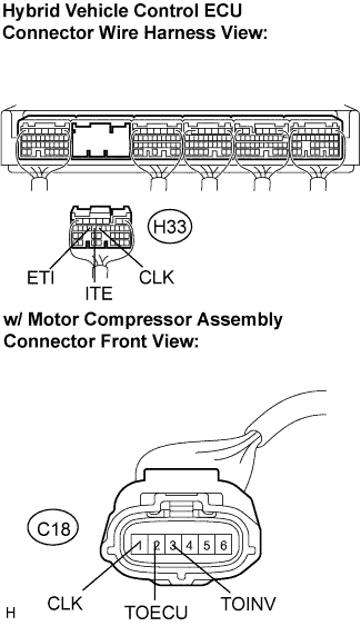
Measure the resistance according to the value(s) in the table below.
- Resistance:
Tester connection
(Symbols)
Condition
Specified condition
C18-1 (CLK) - H33-14 (CLK)
Always
Below 1 Ω
C18-2 (TOECU) - H33-15 (ITE)
Always
Below 1 Ω
C18-3 (TOINV) - H33-16 (ETI)
Always
Below 1 Ω
C18-1 (CLK) - Body ground
Always
10 kΩ or higher
C18-2 (TOECU) - Body ground
Always
10 kΩ or higher
C18-3 (TOINV) - Body ground
Always
10 kΩ or higher
|
|
||||
| OK | |
|
| 6. INSPECT ELECTRIC VEHICLE FUSE |
Turn the ignition switch off.
Remove the service plug grip.
- CAUTION:
- Be sure to wear insulated gloves.
- Do not touch the high-voltage connectors or terminals for 5 minutes after the service plug grip is removed.
- Be sure to wear insulated gloves.
- NOTICE:
- Do not start the engine with the service plug grip removed because it may cause a malfunction.
Remove the inverter cover.
- NOTICE:
- Tape the interlock round terminal for the inverter cover to prevent it from being grounded.
- Be sure to prevent foreign objects or water from entering the w/ converter inverter assembly.
- Tape the interlock round terminal for the inverter cover to prevent it from being grounded.
Check that the A and B bolts are tightened securely.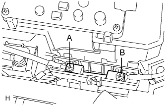
Measure the resistance according to the value(s) in the table below.
- Resistance:
Tester Item
(Tester connection)
Condition
Specified condition
ELECTRIC VEHICLE fuse
(A - B)
Always
Below 1 Ω
|
|
||||
| OK | |
|
| 7. INSPECT W/CONVERTER INVERTER ASSEMBLY |
- CAUTION:
- Be sure to wear insulated gloves.
- Be sure to prevent foreign objects or water from entering the w/ converter inverter assembly.
- Be sure to wear insulated gloves.
Check that the 1 and 2 bolts are tightened securely.
- Torque:
- 8.0 N*m{ 82 kgf*cm , 71 in.*lbf }
Disconnect the connector from the air conditioning wiring harness sub-assembly.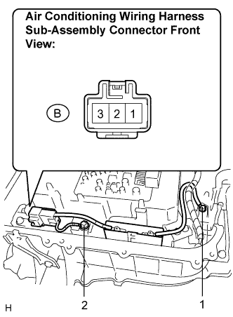
Measure the resistance according to the value(s) in the table below.
- Resistance:
Tester connection
Condition
Specified condition
B-3 - 1
Always
Below 1 Ω
B-1 - 2
Always
Below 1 Ω
|
|
||||
| OK | |
|
| 8. INSPECT ENGINE WIRE NO.4 |
Disconnect the connector from the engine wire No.4.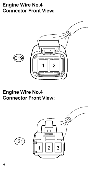
Measure the resistance according to the value(s) in the table below.
- Resistance:
Tester connection
(Symbols)
Condition
Specified condition
C19-1 (PGND) - I21-1
Always
Below 1 Ω
C19-2 (PBAT) - I21-3
Always
Below 1 Ω
C19-1 (PGND) - C19-2 (PBAT)
Always
10 kΩ or higher
|
|
||||
| OK | |
|
| 9. INSPECT W/MOTOR COMPRESSOR ASSEMBLY |
Reconnect the connectors to the engine wire No.4, the air conditioner harness, the hybrid vehicle control ECU and the w/ motor compressor assembly.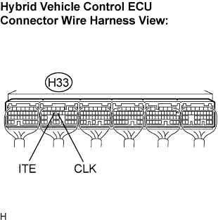
Turn the ignition switch ON.
Measure the waveform according to the condition in the table below.
CLK - Body ground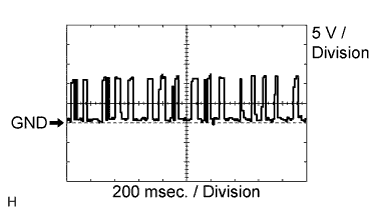
- OK:
- Waveform appears
- HINT:
- Waveform cycle varies with the communication contents.
ITE - Body ground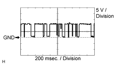
- OK:
- Waveform appears
- HINT:
- Waveform cycle varies with the communication contents.
|
|
||||
| OK | ||
 |
||
| ||