P0A94-588
Diagnostic trouble codes
DESCRIPTION
Refer to the description of the boost converter. (Click here)The boost converter switches the power transistor on and off based on drive signals received from the MG ECU, in order to change the current flowing into the reactor. Also, the boost converter regulates the duration of the switching time through Pulse Width Modulation (PWM) control, in order to control the boosting voltage. The MG ECU monitors the drive signals and detects a malfunction.
| DTC No. |
INF Code |
DTC Detection Condition |
Trouble Area |
| P0A94 |
588 |
Abnormality in boost converter PWM circuit |
|
MONITOR DESCRIPTION
The MG ECU monitors the boost converter PWM circuit. If there is an error in the power transistor actuation signals which are transmitted to the boost converter, the MG ECU interprets this as a malfunction of the boost converter PWM circuit. The HV control ECU illuminates the MIL and sets a DTC.INSPECTION PROCEDURE
- CAUTION:
- Before inspecting the high-voltage system, take safety precautions to prevent electrical shocks, such as wearing insulated gloves and removing the service plug grip. After removing the service plug grip, put it in your pocket to prevent other technicians from reconnecting it while you are working on the high-voltage system.
- After disconnecting the service plug grip, wait for at least 5 minutes before touching any of the high-voltage connectors or terminals.
- Before inspecting the high-voltage system, take safety precautions to prevent electrical shocks, such as wearing insulated gloves and removing the service plug grip. After removing the service plug grip, put it in your pocket to prevent other technicians from reconnecting it while you are working on the high-voltage system.
- HINT:
- At least 5 minutes is required to discharge the high-voltage capacitor inside the w/ converter inverter assembly.
| 1. CHECK CONNECTION CONDITION OF MG ECU CONNECTOR (LOOSENESS AND POOR CONTACT) |

- CAUTION:
- Be sure to wear insulated gloves.
Turn the ignition switch off and remove the service plug grip. (Click here)
- NOTICE:
- Do not put the vehicle into the READY-on state with the service plug grip removed as this may cause a malfunction.
Remove the inverter cover. (Click here)
- NOTICE:
- Wrap the interlock round terminal for the inverter cover with vinyl tape to prevent it from shorting to ground.
- Prevent water in the reservoir tank from entering the inverter.
- Removing the inverter cover causes the MG ECU board to be exposed. Therefore, temporarily install the inverter cover for each area to be inspected.
- Wrap the interlock round terminal for the inverter cover with vinyl tape to prevent it from shorting to ground.
Check the connections of the MG ECU connectors.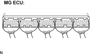

- OK:
- Connectors are connected securely and there is no poor connection.
|
|
||||

| OK | ||
 |
||
| ||