C0200/31
Diagnostic trouble codes
DESCRIPTION
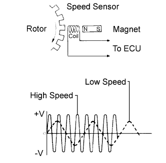

The speed sensor detects wheel speed and sends the appropriate signals to the ECU. These signals are used to control the ABS control system. The front rotors have 48 serrations, respectively.
When the rotors rotate, the magnetic field emitted by the permanent magnet in the speed sensor generates an AC voltage.
Since the frequency of this AC voltage changes in direct proportion to the speed of the rotor, the frequency is used by the ECU to detect the speed of each wheel.
DTCs C1271/71 and C1272/72 can be deleted when the speed sensor sends a vehicle speed signal or the test mode ends. DTCs C1271/71 and C1272/72 are output only in the test mode.
| DTC No. |
INF Code |
DTC Detection Condition |
Trouble Area |
| C0200/31 |
251 |
At a vehicle speed of 6 mph (10 km/h) or more, an open or short in the sensor signal circuit of the abnormal wheel continues for 1 second or more. |
|
| ↑ |
252 |
More than 1 wheel is abnormal. |
↑ |
| ↑ |
253 |
Speed sensor signal circuit is open for 0.5 seconds or more. |
↑ |
| ↑ |
254 |
Momentary interruption of sensor signal from the abnormal wheel occurs 255 times or more. |
↑ |
| ↑ |
255 |
Frequency of 2.7 kHz or higher is input. |
|
| ↑ |
256 |
Rotating direction of each wheel changes 7 times with the ignition switch on while driving at 6 mph (10 km/h) or more. |
|
| ↑ |
257 |
Rotating direction of one of the wheels is not the same as that of the other wheels for 1 second while driving at 18 mph (30 km/h) or more. |
↑ |
| ↑ |
258 |
Rotating direction of one of the wheels is not detected normally, and the rotating direction of each of the other wheels is not the same for 1 second while driving at 18 mph (30 km/h) or more. |
↑ |
| ↑ |
259 |
3 of the wheel sensors detect normal reversing signals, and the other wheel sensor detects malfunction signals 75 times with the ignition switch on while reversing at 1.8 mph (3 km/h). |
↑ |
| ↑ |
260 |
At a vehicle speed of 6 mph (10 km/h) or more, the output from the vehicle speed sensor is halved for 5 seconds or more. |
↑ |
| ↑ |
261 |
Reversing signal is output for 1 second or more while driving at 60 mph (100 km/h) or more. |
↑ |
| ↑ |
262 |
With the voltage of IG1 terminal 9.5 V or more, the sensor power supply voltage decreases for 0.5 seconds or more. |
|
| C0205/32 |
264 |
At a vehicle speed of 6 mph (10 km/h) or more, an open or short in the sensor signal circuit of the abnormal wheel continues for 1 second or more. |
|
| ↑ |
265 |
More than 1 wheel is abnormal. |
↑ |
| ↑ |
266 |
Speed sensor signal circuit is open for 0.5 seconds or more. |
↑ |
| ↑ |
267 |
Momentary interruption of sensor signal from the abnormal wheel occurs 255 times or more. |
↑ |
| ↑ |
268 |
Frequency of 2.7 kHz or higher is input. |
|
| ↑ |
269 |
Rotating direction of each wheel changes 7 times with the ignition switch on while driving at 6 mph (10 km/h) or more. |
|
| ↑ |
270 |
Rotating direction of one of the wheels is not the same as that of the other wheels for 1 second while driving at 18 mph (30 km/h) or more. |
↑ |
| ↑ |
271 |
Rotating direction of one of the wheels is not detected normally, and the rotating direction of each of the other wheels is not the same for 1 second while driving at 18 mph (30 km/h) or more. |
↑ |
| ↑ |
272 |
3 of the wheel sensors detect normal reversing signals, and the other wheel sensor detects malfunction signals 75 times with the ignition switch on while reversing at 1.8 mph (3 km/h). |
↑ |
| ↑ |
273 |
At a vehicle speed of 6 mph (10 km/h) or more, the output from the vehicle speed sensor is halved for 5 seconds or more. |
↑ |
| ↑ |
274 |
Reversing signal is output for 1 second or more while driving at 60 mph (100 km/h) or more. |
↑ |
| ↑ |
275 |
With the voltage of IG1 terminal 9.5 V or more, the sensor power supply voltage decreases for 0.5 seconds or more. |
|
- HINT:
- DTC C0200/31 is for the right front speed sensor.
- DTC C0205/32 is for the left front speed sensor.
- The BRAKE warning light comes on when speed sensor malfunctions are detected in two or more wheels.
- DTC C0200/31 is for the right front speed sensor.
WIRING DIAGRAM
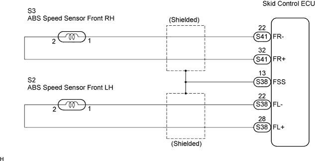
INSPECTION PROCEDURE
- NOTICE:
- When replacing the skid control ECU, perform initialization of liner solenoid valve and calibration (Click here).
| 1. CHECK HARNESS AND CONNECTOR (MOMENTARY INTERRUPTION) |

Using the intelligent tester, check for any momentary interruption in the wire harness and connector corresponding to a DTC (Click here).
ABS / VSC / TRAC: Item
Measurement Item /
Range (Display)
Normal Condition
FR Speed Open
FR speed sensor open detection /
NORMAL or ERROR
NORMAL : Normal condition
FL Speed Open
FR speed sensor open detection /
NORMAL or ERROR
NORMAL : Normal condition
- OK:
- There are no momentary interruptions.
- HINT:
- Perform the above inspection before removing the sensor and connector.
|
|
||||

| OK | |
 |
| 2. READ VALUE OF INTELLIGENT TESTER (FRONT SPEED SENSOR) |
Connect the intelligent tester to the DLC3.
Turn the ignition switch ON position.
Select the DATA LIST mode on the intelligent tester.
ABS / VSC / TRAC: Item
Measurement Item /
Range (Display)
Normal Condition
FR Wheel Speed
Wheel speed sensor (FR) reading /
min.: 0 km/h (0 MPH), max.: 326 km/h (202 MPH)
Actual wheel speed
FL Wheel Speed
Wheel speed sensor (FL) reading /
min.: 0 km/h (0 MPH), max.: 326 km/h (202 MPH)
Actual wheel speed
Check that there is no difference between the speed value output from the speed sensor displayed on the intelligent tester and the speed value displayed on the speedometer when driving the vehicle.
- OK:
- There is almost no difference from the displayed speed value.
- HINT:
- There is tolerance of +-10 % in the speedometer indication.
|
|
||||
| NG | |
|
| 3. INSPECT FRONT SPEED SENSOR INSTALLATION |
Check the sensor installation.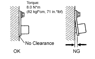
- OK:
- There is no clearance between the sensor and rear axle carrier.
- The installation bolt is tightened properly.
Torque: 8.0 N*m (82 kgf*cm, 71 in.*lbf)
- NOTICE:
- Check the speed sensor signal after the replacement (Click here).
|
|
||||

| OK | |
|
| 4. INSPECT FRONT SPEED SENSOR |
Make sure that there is no looseness at the connector's locking part and connecting part of the connector.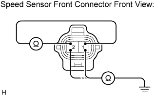
Disconnect the speed sensor connector.
Measure the resistance according to the value(s) in the table below.
- Resistance:
- LH:
Tester Connection
Specified Condition
2 (FL+) - 1 (FL-)
1.4 to 1.8 kΩ
- RH:
Tester Connection
Specified Condition
2 (FR+) - 1 (FR-)
1.4 to 1.8 kΩ
Measure the resistance according to the value(s) in the table below.
- Resistance:
- LH:
Tester Connection
Specified Condition
1 (FL-) - Body ground
10 kΩor higher
2 (FL+) - Body ground
10 kΩor higher
- RH:
Tester Connection
Specified Condition
1 (FR-) - Body ground
10 kΩor higher
2 (FR+) - Body ground
10 kΩor higher
- NOTICE:
- Check the speed sensor signal after replacement (Click here).
|
|
||||
| OK | |
|
| 5. CHECK HARNESS AND CONNECTOR (BETWEEN FRONT SPEED SENSOR AND SKID CONTROL ECU) |
Disconnect the skid control ECU connectors and the front speed sensor connectors.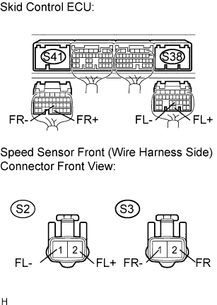
Measure the resistance according to the value(s) in the table below.
- Resistance:
- LH:
Tester Connection
Specified Condition
S2-1 (FL-) - S38-22 (FL-)
Below 1 Ω
S2-2 (FL+) - S38-28 (FL+)
Below 1 Ω
- RH:
Tester Connection
Specified Condition
S3-1 (FR-) - S41-22 (FR-)
Below 1 Ω
S3-2 (FR+) - S41-32 (FR+)
Below 1 Ω
Measure the resistance according to the value(s) in the table below.
- Resistance:
- LH:
Tester Connection
Specified Condition
S2-2 (FL+) - Body ground
10 kΩ or higher
S2-1 (FL-) - Body ground
10 kΩ or higher
- RH:
Tester Connection
Specified Condition
S3-2 (FR+) - Body ground
10 kΩ or higher
S3-1 (FR-) - Body ground
10 kΩ or higher
|
|
||||
| OK | |
|
| 6. INSPECT SPEED SENSOR AND SENSOR ROTOR SERRATIONS |
 |
Connect the skid control ECU connectors.
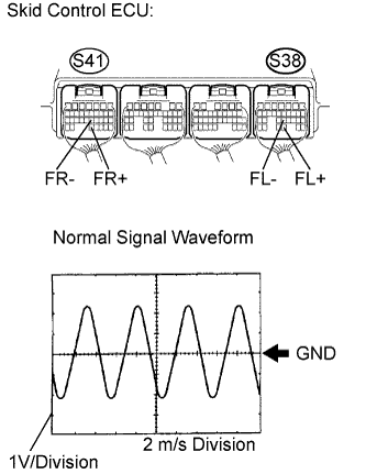
Connect the oscilloscope to terminals S41-32 (FR+) and S41-22 (FR-) or S38-28 (FL+) and S38-22 (FL-) of the skid control ECU.
Drive the vehicle at approximately 19 mph (30 km/h), and check the signal waveform.
- OK:
- A waveform as shown in the figure should be output.
- HINT:
- As the vehicle speed (wheel revolution speed) increases, a cycle of the waveform narrows and the fluctuation in the output voltage becomes greater.
- When noise is identified in the waveform on the oscilloscope, error signals are generated due to the speed sensor rotor's scratches, looseness or foreign matter attached to it.
- As the vehicle speed (wheel revolution speed) increases, a cycle of the waveform narrows and the fluctuation in the output voltage becomes greater.
|
|
||||
| OK | |
|
| 7. READ VALUE OF INTELLIGENT TESTER |
Connect the intelligent tester to the DLC3.
Turn the ignition switch on.
Select the DATA LIST mode on the intelligent tester.
ABS / VSC / TRAC: Item
Measurement Item /
Range (Display)
Normal Condition
FR Wheel Speed
Wheel speed sensor (FR) reading /
min.: 0 km/h (0 MPH), max.: 326 km/h (202 MPH)
Actual wheel speed
FL Wheel Speed
Wheel speed sensor (FL) reading /
min.: 0 km/h (0 MPH), max.: 326 km/h (202 MPH)
Actual wheel speed
Check that there is no difference between the speed value output from the speed sensor displayed on the intelligent tester and the speed value displayed on the speedometer when driving the vehicle.
- OK:
- There is almost no difference from the displayed speed value.
- HINT:
- There is tolerance of +- 10 % in the speedometer indication.
|
|
||||
| OK | ||
 |
||
| ||
| 8. PERFORM TEST MODE (SIGNAL CHECK) |
Perform sensor signal check in TEST MODE PROCEDURE (Click here).
- OK:
- All test mode DTCs are erased.
|
|
||||
| OK | |
|
| 9. INSPECT SPEED SENSOR AND SENSOR ROTOR SERRATIONS |
Connect the oscilloscope to terminals S41-32 (FR+) and S41-22 (FR-) or S38-28 (FL+) and S38-22 (FL-) of the skid control ECU.
Drive the vehicle at approximately 19 mph (30 km/h), and check the signal waveform.
- OK:
- A waveform as shown in the figure should be output.
- HINT:
- As the vehicle speed (wheel revolution speed) increases, a cycle of the waveform narrows and the fluctuation in the output voltage becomes greater.
- When noise is identified in the waveform on the oscilloscope, error signals are generated due to the speed sensor rotor's scratches, looseness or foreign matter attached to it.
- As the vehicle speed (wheel revolution speed) increases, a cycle of the waveform narrows and the fluctuation in the output voltage becomes greater.
|
|
||||
| OK | ||
|
||
| ||
| 10. REPAIR OR REPLACE HARNESS OR CONNECTOR (BETWEEN FRONT SPEED SENSOR AND SKID CONTROL ECU) |
| NEXT | |
|
| 11. RECONFIRM DTC |
Clear the DTC (Click here).
Turn the ignition switch on.
Drive the vehicle at the speed of 32 km/h (20 mph) or more, for 60 seconds or more, and drive in reverse at a speed of 3 km/h (2 mph) or more, for approximately 5 seconds.
Check that the same DTC is recorded (Click here).
- HINT:
- Reinstall the sensors, connectors, etc. and restore the previous vehicle conditions before rechecking for DTCs.
- Result:
Condition
Proceed To
DTC is not output
A
DTC is output
B
|
|
||||
| A | ||
|
||
| ||