C1511 Torque sensor (TRQ1) signal error or stop
Diagnostic trouble codes
DESCRIPTION
The torque sensor converts rotation torque input to the steering wheel into an electrical signal and sends it to the ECU. Based on this signal, the ECU detects steering effort.| DTC No. |
Detection Item |
Trouble Area |
| C1511 |
Torque sensor (TRQ1) signal error or stop |
|
| C1512 |
Torque sensor (TRQ2) signal error or stop |
|
| C1513 |
Deviation between torque sensors TRQ1 and TRQ2 is out of specification |
|
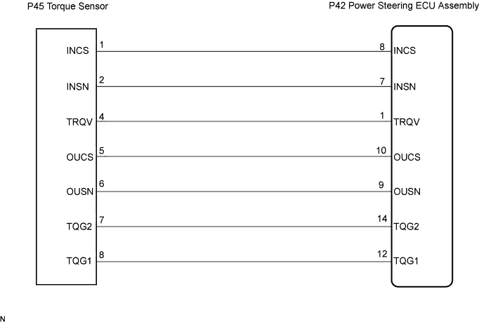
WIRING DIAGRAM

INSPECTION PROCEDURE
| 1. CHECK HARNESS AND CONNECTOR (BETWEEN POWER STEERING ECU ASSEMBLY AND TORQUE SENSOR) |

Disconnect the P42 connector from the power steering ECU assembly.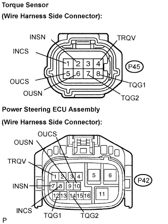
Disconnect the P45 connector from the torque sensor.
Measure the resistance according to the value(s) in the table below.
- Resistance:
Tester connection
(Symbols)
Condition
Specified condition
P45-1 (INCS) - P42-8 (INCS)
Always
Below 1 Ω
P45-2 (INSN) - P42-7 (INSN)
Always
Below 1 Ω
P45-4 (TRQV) - P42-1 (TRQV)
Always
Below 1 Ω
P45-5 (OUCS) - P42-10 (OUCS)
Always
Below 1 Ω
P45-6 (OUSN) - P42-9 (OUSN)
Always
Below 1 Ω
P45-7 (TQG2) - P42-14 (TQG2)
Always
Below 1 Ω
P45-8 (TQG1) - P42-12 (TQG1)
Always
Below 1 Ω
P45-1 (INCS) - Body ground
Always
10 kΩ or higher
P45-2 (INSN) - Body ground
Always
10 kΩ or higher
P45-4 (TRQV) - Body ground
Always
10 kΩ or higher
P45-5 (OUCS) - Body ground
Always
10 kΩ or higher
P45-6 (OUSN) - Body ground
Always
10 kΩ or higher
P45-7 (TQG2) - Body ground
Always
10 kΩ or higher
P45-8 (TQG1) - Body ground
Always
10 kΩ or higher
|
|
||||

| OK | |
 |
| 2. INSPECT POWER STEERING LINK ASSEMBLY (TORQUE SENSOR) |
Measure the resistance according to the value(s) in the table below.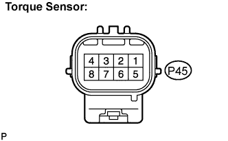
- Resistance:
Tester connection
(Symbols)
Condition
Specified condition
P45-1 (INCS) - P45-7 (TQG2)
Always
90 to 170 Ω
P45-2 (INSN) - P45-7 (TQG2)
Always
300 to 430 Ω
P45-4 (TRQV) - P45-8 (TQG1)
Always
4 to 14 Ω
P45-5 (OUCS) - P45-7 (TQG2)
Always
90 to 170 Ω
P45-6 (OUSN) - P45-7 (TQG2)
Always
300 to 430 Ω
- NOTICE:
- If replacing the power steering link assembly, clear the rotation angle sensor calibration value, initialize the rotation angle sensor value, and calibrate torque sensor zero point (Click here).
|
|
||||
| OK | |
|
| 3. REPLACE POWER STEERING ECU ASSEMBLY |
Replace the power steering ECU assembly (Click here).
| NEXT | |
|
| 4. INITIALIZE ROTATION ANGLE SENSOR VALUE AND CALIBRATE TORQUE SENSOR ZERO POINT |
Initialize the rotation angle sensor value and calibrate the torque sensor zero point (Click here).
| NEXT | |
|
| 5. RECONFIRM DTC |
Check for DTCs (Click here).
Is DTC C1511, C1512 or C1513 output?
- OK:
- DTC is not output.
- NOTICE:
- If replacing the power steering link assembly, clear the rotation angle sensor calibration value, initialize the rotation angle sensor value, and calibrate torque sensor zero point (Click here).
|
|
||||
| OK | ||
 |
||
| ||