C1202/68
Diagnostic trouble codes
DESCRIPTION
When a fluid level drop in the master cylinder reservoir is detected, the signal is input to the skid control ECU.When the DTC for the fluid level drop is memorized, the warning is canceled if the fluid level returns to normal and the other DTCs are not input.
| DTC No. |
INF Code |
DTC Detecting Condition |
Trouble Area |
| C1202/68 |
511 |
|
|
| C1202/68 |
512 |
|
|
WIRING DIAGRAM
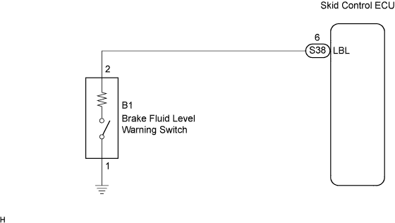

INSPECTION PROCEDURE
- NOTICE:
- When replacing the skid control ECU assembly, perform initialization of the linear solenoid valve and calibration (Click here).
- HINT:
- Before releasing the parking brake, set the chocks to hold the vehicle for safety.
| 1. CHECK BRAKE FLUID LEVEL IN RESERVOIR |

Check that the brake fluid level is sufficient.
- HINT:
- If the fluid level drops, check for a fluid leak, and repair if found.
- If no leaks exist, add and adjust fluid and then check that the trouble code is not output again.
- If the fluid level drops, check for a fluid leak, and repair if found.
- OK:
- Brake fluid level is proper.
|
|
||||

| OK | |
 |
| 2. INSPECT BRAKE FLUID LEVEL WARNING SWITCH |
Remove the reservoir tank cap and strainer.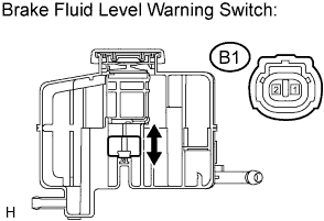
Disconnect the brake fluid level warning switch connector.
Measure the resistance according to the value(s) in the table below.
- Resistance:
Tester Connection
Fluid Level
Specified Condition
(B1-1) - (B1-2)
Proper
1.84 to 2.16 kΩ
(B1-1) - (B1-2)
Below min.: level
Below 1 Ω
|
|
||||
| OK | |
|
| 3. CHECK HARNESS AND CONNECTOR (BETWEEN SKID CONTROL ECU AND FLUID LEVEL WARNING SWITCH) |
Disconnect the skid control ECU connector and the brake fluid level warning switch connector.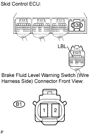
Measure the resistance according to the value(s) in the table below.
- Resistance:
Tester Connection
Specified Condition
S38-6 (LBL) - (B1-2)
Below 1 Ω
Measure the resistance according to the value(s) in the table below.
- Resistance:
Tester Connection
Specified Condition
S38-6 (LBL) - Body ground
10 kΩ or higher
|
|
||||
| OK | |
|
| 4. RECONFIRM DTC |
Clear the DTCs (Click here).
Turn the ignition switch on.
Check the same DTCs are recorded (Click here).
- Result:
Condition
Proceed To
DTC is output
A
DTC is not output
B
- HINT:
- This DTC may be memorized due to a malfunction in the connector terminal connection, etc.
|
|
||||
| A | ||
 |
||
| ||