C1311/11
Diagnostic trouble codes
DESCRIPTION
ABS main relay 1 (ABS No.1 relay) supplies power to the changeover solenoid and the linear solenoid.ABS main relay 2 (ABS No.2 relay) goes on for approximately 5 seconds after the ignition switch is turned off and the braking effort signal input is terminated. ABS main relay 2 (ABS No.2 relay) supplies electricity and maintains operating condition for the brake system when the ignition switch is off.
| DTC No. |
INF Code |
DTC Detecting Condition |
Trouble Area |
| C1311/11 |
1 |
|
|
| C1312/12 |
3 |
Relay contact is on for at least 4 sec. when main relay 1 is off. |
|
| C1313/13 |
4 |
|
|
| C1314/14 |
6 |
Relay contact is on for at least 4 sec. when main relay 2 is off. |
|
WIRING DIAGRAM
Refer to DTCs C1241/41 and C1242/42 (Click here).INSPECTION PROCEDURE
- NOTICE:
- When replacing the skid control ECU, perform initialization of linear solenoid valve and calibration (Click here).
| 1. PERFORM ACTIVE TEST BY INTELLIGENT TESTER (ABS NO.1 RELAY, ABS NO.2 RELAY) |

Connect the intelligent tester to the DLC3.
Turn the ignition switch on.
Select the ACTIVE TEST mode on the intelligent tester.
Check the operation sound of the ABS No.1 and No.2 relays.
Item
Vehicle Condition / Test Details
Diagnostic Note
ECB Main Relay
Turns ABS No.1 relay ON/OFF
Operating of solenoid
(clicking sound) can be heard
ECB Main Relay 2
Turns ABS No.2 relay ON/OFF
Operating of solenoid
(clicking sound) can be heard
- OK:
- Operating sound of ABS No.1 and ABS No.2 relays should be heard.
|
|
||||

| OK | |
 |
| 2. INSPECT ABS MAIN RELAY (ABS NO.1 RELAY, ABS NO.2 RELAY) |
Remove the ABS No.1 relay and ABS No.2 relay.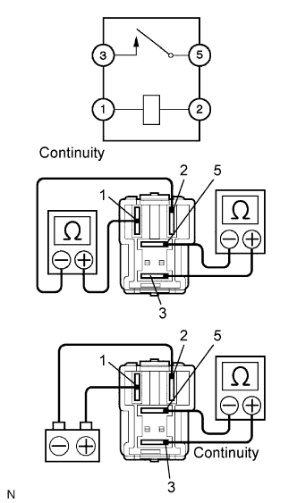

Measure the resistance according to the value(s) in the table below.
- Resistance:
Tester Connection
Specified Condition
Terminal 1 - Terminal 2
100 Ω
Terminal 3 - Terminal 5
10 kΩ or higher (No Continuity)
Apply battery voltage between terminals 1 and 2.
Measure the resistance according to the value(s) in the table below.
- Resistance:
Tester Connection
Specified Condition
Terminal 3 - Terminal 5
Below 1 Ω
|
|
||||

| OK | |
|
| 3. INSPECT FUSE (ABS NO.1, ABS NO.2 AND ABS NO.3 FUSES) |
Remove the ABS No.1, ABS No.2 and ABS No.3 fuses.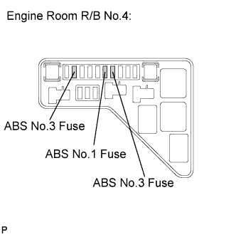
Measure the resistance according to the value(s) in the table below.
- Resistance:
Fuse
Specified Condition
ABS No.1 Fuse
Below 1 Ω (Continuity)
ABS No.2 Fuse
Below 1 Ω (Continuity)
ABS No.3 Fuse
Below 1 Ω (Continuity)
|
|
||||
| OK | |
|
| 4. INSPECT SKID CONTROL ECU (+BI1, +BI2 TERMINAL) |
Measure the voltage according to the value(s) in the table below.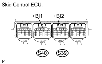
- HINT:
- Measure the voltage from the back side of the connector with the connector connected to the skid control ECU.
- Voltage:
Tester Connection
Specified Condition
S40-3 (+BI1) - Body ground
10 to 14 V
S39-5 (+BI2) - Body ground
10 to 14 V
|
|
||||
| OK | |
|
| 5. INSPECT SKID CONTROL ECU (+BO1, +BO2, R1+, R2+ TERMINAL) |
Measure the voltage according to the value(s) in the table below.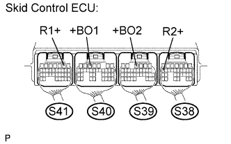
- HINT:
- Measure the voltage from the back side of the connector with the connector connected to the skid control ECU.
- Voltage:
Tester Connection
Specified Condition
S41-2 (R1+) - Body ground
10 to 14 V
S40-5 (+BO1) - Body ground
10 to 14 V
S39-4 (+BO2) - Body ground
10 to 14 V
S38-17 (R2+) - Body ground
10 to 14 V
|
|
||||
| OK | |
|
| 6. INSPECT SKID CONTROL ECU (BS1, BS2 TERMINAL) |
Measure the voltage according to the value(s) in the table below.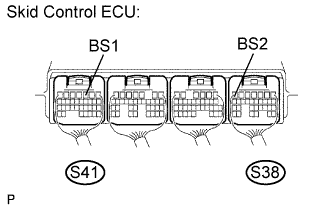
- HINT:
- Measure the voltage from the back side of the connector with the connector connected to the skid control ECU.
- Voltage:
Tester Connection
Specified Condition
S41-3 (BS1) - Body ground
10 to 14 V
S38-7 (BS2) - Body ground
10 to 14 V
|
|
||||
| OK | ||
 |
||
| ||