C1341/62
Diagnostic trouble codes
DESCRIPTION
The skid control ECU controls braking force according to the hybrid system regenerative braking force and inputs the fluid pressure necessary for operating each wheel cylinder according to the wheel cylinder pressure sensor.DTCs may be stored if brake fluid leaks, wheel cylinder vibrates due to uneven wear of the brake disc rotor, or foreign matter enters the solenoid valve.
DTCs may be stored if the line pressure drops during air bleeding.
| DTC No. |
INF Code |
DTC Detecting Condition |
Trouble Area |
| C1341/62 |
551 |
Hydraulic pressure control on FR wheel has deteriorated. |
|
| C1341/62 |
552 |
Hydraulic pressure control on FR wheel has deteriorated. |
|
| C1341/62 |
553 |
There is a malfunction, such as leakage in the pressure increase control valve of FR wheel. |
|
| C1341/62 |
554 |
There is a malfunction, such as leakage in the pressure decrease control valve of FR wheel. |
|
| C1341/62 |
555 |
There is a malfunction, such as leakage in the pressure decrease control valve of FR wheel. |
|
| C1342/63 |
561 |
Hydraulic pressure control on FL wheel has deteriorated. |
|
| C1342/63 |
562 |
Hydraulic pressure control on FL wheel has deteriorated. |
|
| C1342/63 |
563 |
There is a malfunction, such as leakage in pressure increase control valve of FL wheel. |
|
| C1342/63 |
564 |
There is a malfunction, such as leakage in pressure decrease control valve of FL wheel. |
|
| C1342/63 |
565 |
There is a malfunction, such as leakage in pressure decrease control valve of FL wheel. |
|
| C1343/64 |
571 |
Hydraulic pressure control on RR wheel has deteriorated. |
|
| C1343/64 |
572 |
Hydraulic pressure control on RR wheel has deteriorated. |
|
| C1343/64 |
573 |
There is a malfunction, such as leakage in pressure increase control valve of RR wheel. |
|
| C1343/64 |
574 |
There is a malfunction, such as leakage in pressure decrease control valve of RR wheel. |
|
| C1343/64 |
575 |
There is a malfunction, such as leakage in pressure decrease control valve of RR wheel. |
|
| C1344/65 |
581 |
Hydraulic pressure control on RL wheel has deteriorated. |
|
| C1344/65 |
582 |
Hydraulic pressure control on RL wheel has deteriorated. |
|
| C1344/65 |
583 |
There is a malfunction, such as leakage in pressure increase control valve of RR wheel. |
|
| C1344/65 |
584 |
There is a malfunction, such as leakage in pressure decrease control valve of RR wheel. |
|
| C1344/65 |
585 |
There is a malfunction, such as leakage in pressure decrease control valve of RL wheel. |
|
WIRING DIAGRAM
Refer to DTCs C1315/31, C1316/32, C1352/21, C1353/23, C1354/25, C1355/27, C1356/22, C1357/24, C1358/26 and C1359/28 (Click here).INSPECTION PROCEDURE
- NOTICE:
- When replacing the skid control ECU, perform initialization of linear solenoid valve and calibration (Click here).
- HINT:
- When C1364/61 is output together with C1341/62, C1342/63, C1343/64 or C1344/65, inspect and repair the trouble areas indicated by C1364/61 first.
| 1. CHECK BRAKE FLUID LEAKAGE |

Check that there is no fluid leakage in the brake line between the brake actuator and the wheel cylinder which is the cause of DTCs.
Check that the brake is not dragging.
- OK:
- There is no fluid leakage or dragging.
|
|
||||

| OK | |
 |
| 2. PERFORM AIR BLEED |
Bleed the air out of the front and rear systems (Click here).
| NEXT | |
|
| 3. RECONFIRM DTC |
Clear the DTCs (Click here).
Turn the ignition switch on.
Check the same DTCs are recorded (Click here).
- Result:
Condition
Proceed To
DTC is output
A
DTC is not output
B
- HINT:
- DTC may be stored if foreign matter or air enters the solenoid valve.
|
|
||||
| A | |
|
| 4. CHECK HARNESS AND CONNECTOR (BETWEEN SKID CONTROL ECU AND BRAKE ACTUATOR ASSEMBLY) |
Disconnect the skid control ECU connectors and brake actuator connector.
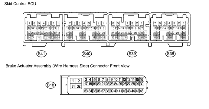

Measure the resistance according to the value(s) in the table below.
- Resistance:
Tester Connection
Tester Connection
S41-6 (FRA-) - B18-43 (SLAFR-)
Below 1 Ω
S41-7 (FRA+) - B18-44 (SLAFR+)
Below 1 Ω
S41-26 (RLR-) - B18-26 (SLRRL-)
Below 1 Ω
S41-16 (RLR+) - B18-25 (SLRRL+)
Below 1 Ω
S41-27 (RLA-) - B18-42 (SLARL-)
Below 1 Ω
S41-15 (RLA+) - B18-41 (SLARL+)
Below 1 Ω
S38-18 (RRR-) - B18-24 (SLRRR-)
Below 1 Ω
S38-20 (RRR+) - B18-23 (SLRRR+)
Below 1 Ω
S38-9 (RRA-) - B18-40 (SLARR-)
Below 1 Ω
S38-19 (RRA+) - B18-39 (SLARR+)
Below 1 Ω
S38-26 (FLR-) - B18-22 (SLRFL-)
Below 1 Ω
S38-8 (FLR+) - B18-21 (SLRFL+)
Below 1 Ω
S38-2 (FLA-) - B18-38 (SLAFL-)
Below 1 Ω
S38-1 (FLA+) - B18-35 (SLAFL+)
Below 1 Ω
S41-34 (FRR-) - B18-27 (SLRFR-)
Below 1 Ω
S41-17 (FRR+) - B18-28 (SLRFR+)
Below 1 Ω
Measure the resistance according to the value(s) in the table below.
- Resistance:
Tester Connection
Tester Connection
S41-6 (FRA-) - Body ground
10 kΩ or higher
S41-7 (FRA+) - Body ground
10 kΩ or higher
S41-15 (RLA+) - Body ground
10 kΩ or higher
S41-16 (RLR+) - Body ground
10 kΩ or higher
S41-17 (FRR+) - Body ground
10 kΩ or higher
S41-26 (RLR-) - Body ground
10 kΩ or higher
S41-27 (RLA-) - Body ground
10 kΩ or higher
S41-34 (FRR-) - Body ground
10 kΩ or higher
S38-1 (FLA+) - Body ground
10 kΩ or higher
S38-2 (FLA-) - Body ground
10 kΩ or higher
S38-8 (FLR+) - Body ground
10 kΩ or higher
S38-9 (RRA-) - Body ground
10 kΩ or higher
S38-18 (RRR-) - Body ground
10 kΩ or higher
S38-19 (RRA+) - Body ground
10 kΩ or higher
S38-20 (RRR+) - Body ground
10 kΩ or higher
S38-26 (FLR-) - Body ground
10 kΩ or higher
|
|
||||
| OK | |
|
| 5. READ VALUE OF INTELLIGENT TESTER (WHEEL CYLINDER PRESSURE SENSOR) |
Connect the pedal effort gauge.
Install the LSPV gauge (SST) and bleed air (Click here).
- SST
- 09709-29018
Connect the intelligent tester to the DLC3.
Select the DATA LIST mode on the intelligent tester.
ABS / VSC / TRAC: Item
Measurement Item /
Range (Display)
Normal Condition
FR W/C Sensor
Front right wheel cylinder pressure sensor /
min.: 0 V, max.: 5 V
When brake pedal is released:
0.3 to 0.9 V
FL W/C Sensor
Front left wheel cylinder pressure sensor /
min.: 0 V, max.: 5 V
When brake pedal is released:
0.3 to 0.9 V
RR W/C Sensor
Rear right wheel cylinder pressure sensor /
min.: 0 V, max.: 5 V
When brake pedal is released:
0.3 to 0.9 V
RL W/C Sensor
Rear left wheel cylinder pressure sensor /
min.: 0 V, max.: 5 V
When brake pedal is released:
0.3 to 0.9 V
Check the output value of the wheel cylinder pressure at each fluid pressure during the ECB control.
- Voltage:
Front wheel cylinder pressure sensor Fluid Pressure
MPa (kgf/cm2, psi)
FR PRESS SENS
(DATA-LIST)
FL PRESS SENS
(DATA-LIST)
2.6 (26.5, 376.9)
0.85 to 1.15 V
0.85 to 1.15 V
6.3 (64.3, 914.5)
1.6 to 1.9 V
1.6 to 1.9 V
8.1 (82.6, 1174.8)
1.95 to 2.25 V
1.95 to 2.25 V
8.2 (83.6, 1189.0)
2.0 to 2.3 V
2.0 to 2.3 V
Rear wheel cylinder pressure sensor Fluid Pressure
MPa (kgf/cm2, psi)
RR PRESS SENS
(DATA-LIST)
RL PRESS SENS
(DATA-LIST)
2.7 (27.5, 391.1)
0.85 to 1.15 V
0.85 to 1.15 V
5.0 (51.0, 725.4)
1.35 to 1.65 V
1.35 to 1.65 V
|
|
||||
| OK | |
|
| 6. CHECK BRAKE DISC |
Disconnect the brake pedal stroke sensor connector.
Carry out the running and braking test according to freeze frame data or customer problem analysis. Check the brake line pressure vibration caused due to uneven wear of the disc according to brake pedal vibration.
- OK:
- Brake pedal does not vibrate during braking.
- HINT:
- The brake pedal does not kick back due to wheel cylinder piston vibration during ECB control.
- If the brake pedal stroke sensor connector is disconnected, the fail-safe function prohibits ECB control.
- The active test does not prohibit ECB control when the vehicle is running, so disconnect the stroke sensor connector and carry out inspection.
- Disc wear can be checked by measuring the disc thickness.
- The brake pedal does not kick back due to wheel cylinder piston vibration during ECB control.
|
|
||||
| OK | ||
 |
||
| ||