P0325 Knock sensor signal level remains at low for more than 10 seconds
Diagnostic trouble codes
DESCRIPTION
A flat type knock sensor (non-resonant type) has the structure that can detect the vibration in a wider band of frequency from about 6 kHz to 15 kHz and has the following features.Knock sensors are fitted on the right bank and left bank of the cylinder block to detect engine knocking. Each knock sensor contains a piezoelectric element which generates voltage when it becomes deformed. Generation of the voltage occurs when the cylinder block vibrates due to knocking. If engine knocking occurs, the ignition timing is retarded in order to suppress the knocking.
| DTC No. |
DTC Detection Condition |
Trouble Area |
| P0325 P0330 |
Knock sensor signal level remains at low for more than 10 seconds |
|
| P0327 P0332 |
Output voltage of the knock sensor 1 or 2 is 0.5 V or less |
|
| P0328 P0333 |
Output voltage of the knock sensor 1 or 2 is 4.5 V or more |
|
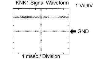

| Item |
Details |
| Terminal |
KNK1 - EKNK or KNK2 - EKN2 |
| Equipment Settings |
0.01 to 10 V/Division, 0.01 to 10 msec./Division |
| Condition |
After warming up the engine, keep the engine speed at 4,000 rpm. |
WIRING DIAGRAM
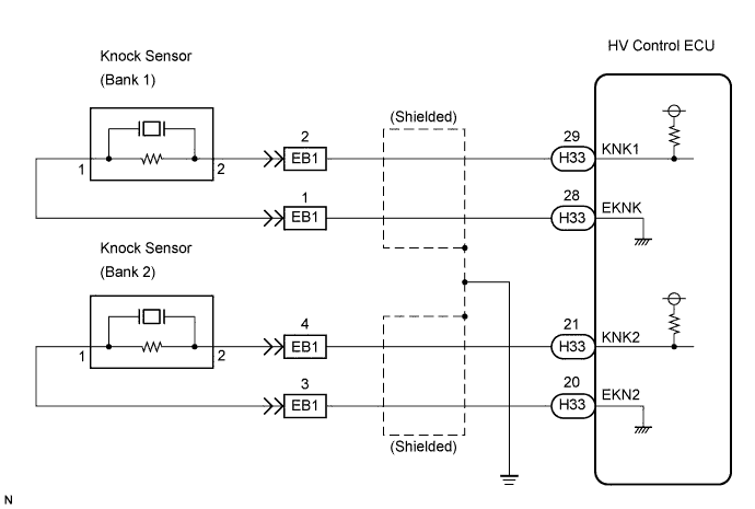
INSPECTION PROCEDURE
- HINT:
- DTC P0325, P0327 and P0328 are for the bank 1 knock sensor circuit.
- DTC P0330, P0332 and P0333 are for the bank 2 knock sensor circuit.
- Read freeze frame data using the intelligent tester. The ECM records vehicle and driving condition information as freeze frame data the moment a DTC is stored. When troubleshooting, freeze frame data can help determine if the vehicle was running or stopped, if the engine was warmed up or not, if the air-fuel ratio was lean or rich, and other data from the time the malfunction occurred.
- DTC P0325, P0327 and P0328 are for the bank 1 knock sensor circuit.
| 1. READ OUTPUT DTC (CHECK KNOCK SENSOR CIRCUIT) |

Disconnect the EB1 connector.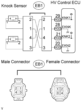
Using lead wires, connect the EB1 terminals as follows.
Male Connector - Female Connector
Terminal 2 - Terminal 4
Terminal 1- Terminal 3
Terminal 4- Terminal 2
Terminal 3- Terminal 1
Warm up the engine.
Run the engine at 3,000 rpm for 10 seconds or more.
Connect the intelligent tester to the DLC3.
Turn the ignition switch to ON and turn the intelligent tester ON.
Select the item: Powertrain / Engine /DTC.
Read DTCs.
- Result:
Display
Proceed to
DTCs same as when vehicle brought in
P0325, P0327, P0328 → P0325, P0327, P0328
or
P0330, P0332, P0333 → P0330, P0332, P0333
A
DTCs different from when vehicle brought in
P0325 → P0330
or
P0330 → P0325
B
DTCs different from when vehicle brought in
P0327, P0328 → P0332, P0333
or
P0332, P0333 → P0327, P0328
C
Reconnect the EB1 connector.
|
|
||||
|
|
||||

| A | |
 |
| 2. CHECK HARNESS AND CONNECTOR |
Disconnect the EB1 connector.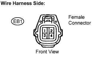
Disconnect the H33 HV Control ECU connector.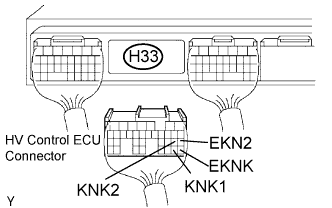
Measure the resistance between the wire harness side connectors.
- Standard resistance (Check for open):
Tester Connection
Specified Condition
EB1 female connector 2 - KNK1 (H33-29)
Below 1 Ω
EB1 female connector 1- EKNK (H33-28)
EB1 female connector 4 - KNK2 (H33-21)
EB1 female connector 3 - EKN2 (H33-20)
- Standard resistance (Check for short):
Tester Connection
Specified Condition
EB1 female connector 2 or KNK1 (H33-29) - Body ground
10 kΩ or higher
EB1 female connector 1 or EKNK (H33-28) - Body ground
EB1 female connector 4 or KNK2 (H33-21) - Body ground
EB1 female connector 3 or EKN2 (H33-20) - Body ground
Reconnect the EB1 connector.
Reconnect the ECM connector.
|
|
||||

| OK | |
|
| 3. CHECK HV CONTROL ECU |
Disconnect the H33 HV Control ECU connector.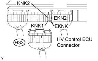
Turn the ignition switch to ON.
Measure the voltage between the specified ECM terminals
- Standard voltage:
Tester Connection
Specified Condition
KNK1 (H33-29) - EKNK (H33-28)
4.5 to 5.5 V
KNK2 (H33-21) - EKN2 (H33-20)
Reconnect the ECM connector.
|
|
||||
| OK | ||
 |
||
| ||
| 4. CHECK KNOCK SENSOR (SENSOR INSTALLATION) |
Check the installation condition of the knock sensors.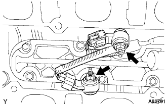
- Torque:
- 20 N*m{ 204 kgf*cm , 15 ft.*lbf }
|
|
||||
| OK | ||
|
||
| ||
| 5. CHECK KNOCK CONTROL SENSOR (SENSOR RESISTANCE) |
Disconnect the EB1 connector.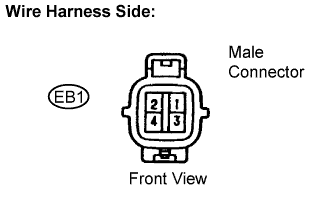
Measure the resistance between the terminals of the EB1 male connector.
- Standard resistance:
Tester Connection
Specified Condition
EB1 male connector 2 - 1
120 to 280 kΩ
EB1 male connector 4- 3
Reconnect the EB1 connector.
|
|
||||
| NG | |
|
| 6. CHECK HARNESS AND CONNECTOR (EA1 CONNECTOR - KNOCK SENSOR) |
- HINT:
- If DTC P0327 or P0328 has changed to P0332 or P0333, check the knock sensor circuit on the right bank side.
- If DTC P0332 or P0333 has changed to P0327 or P0328, check the knock sensor circuit on the left bank side.
- If DTC P0327 or P0328 has changed to P0332 or P0333, check the knock sensor circuit on the right bank side.
Disconnect the EB1 connector.
Disconnect the K3 or K5 knock sensor connector.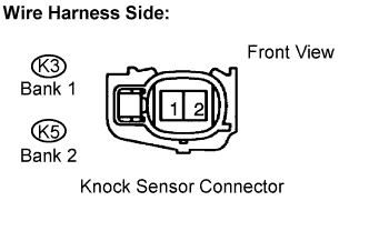
Measure the resistance between the wire harness side connectors.
- Standard resistance (Check for open):
Tester Connection
Specified Condition
EB1 male connector 2 - K3-2
Below 1 Ω
EB1 male connector 1- K3-1
EB1 male connector 4 - K5-2
EB1 male connector 3 - K5-1
- Standard resistance (Check for short):
Tester Connection
Specified Condition
EB1 male connector 2 - K3-2 or Body ground
10 kΩ or higher
EB1 male connector 1- K3-1 or Body ground
EB1 male connector 4 - K5-2 or Body ground
EB1 male connector 3 or K5-1 - Body ground
Reconnect the EB1 connector.
Reconnect the knock sensor connector.
|
|
||||
| OK | ||
|
||
| ||