INSTALLATION
Removal / installation
| 1. INSTALL FRONT LOWER BALL JOINT |

Install the front lower ball joint to the steering knuckle with the nut.
- Torque:
- 123 N*m{ 1,250 kgf*cm , 91 ft.*lbf }
- NOTICE:
- Prevent oil from adhering to the screw and tapered parts.
Install a new cotter pin.
- NOTICE:
- If the holes for the cotter pin are not aligned, tighten the nut further up to 60°.
| 2. INSTALL FRONT AXLE HUB BEARING |
Using SST and a press, install a new front axle hub bearing to the steering knuckle.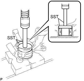

- SST
- 09950-60020
(09951-00810)
09950-70010 (09951-07100)
| 3. INSTALL FRONT DISC BRAKE DUST COVER |
Install the disc brake dust cover to the steering knuckle with the 4 bolts.
- Torque:
- 8.3 N*m{ 85 kgf*cm , 73 in.*lbf }
| 4. INSTALL FRONT AXLE HUB |
Using SST and a press, install the front axle hub sub-assembly.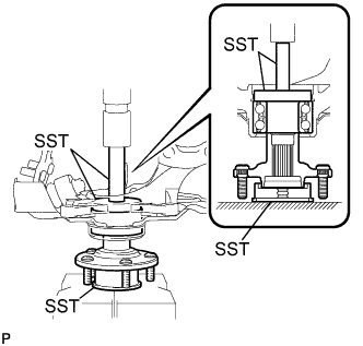
- SST
- 09608-32010
09950-60020 (09951-00810)
09950-70010 (09951-07100)
| 5. INSTALL FRONT AXLE HUB HOLE SNAP RING |
Using snap ring pliers, install a new front axle hub hole snap ring.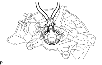
| 6. INSTALL FRONT WHEEL NO.1 BEARING DUST DEFLECTOR |
Using SST and a hammer, install the bearing dust deflector No.1.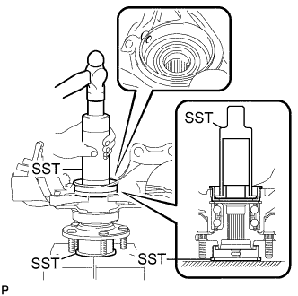
- SST
- 09316-60011
(09316-00011, 09316-00031)
09608-32010
- HINT:
- Align the hole for the speed sensor in the bearing dust deflector No.1 with the steering knuckle.
| 7. INSTALL FRONT AXLE ASSEMBLY |
Install the front axle assembly to the front drive shaft assembly.
- NOTICE:
- Be careful not to damage the outboard joint boot and speed sensor rotor.
- Prevent foreign matter from adhering to the speed sensor rotor.
- Be careful not to damage the outboard joint boot and speed sensor rotor.
Install the front axle assembly to the front shock absorber assembly with the 2 bolts and nuts.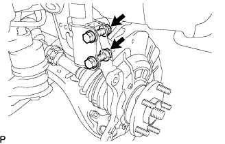
- Torque:
- 290 N*m{ 3,000 kgf*cm , 217 ft.*lbf }
- HINT:
- Insert the bolt from the front side of the vehicle and tighten the nut.
| 8. INSTALL FRONT SUSPENSION NO. 1 LOWER ARM |
Install the lower ball joint to the front suspension arm sub-assembly lower with the bolt and 2 nuts.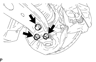
- Torque:
- 127 N*m{ 1,300 kgf*cm , 94 ft.*lbf }
| 9. CONNECT TIE ROD ASSEMBLY |
Install the tie rod end to the steering knuckle with the nut.
- Torque:
- 49 N*m{ 500 kgf*cm , 36 ft.*lbf }
Install a new cotter pin.
- NOTICE:
- If the holes for the cotter pin are not aligned, tighten the castle nut up to 60° further.
| 10. INSTALL FRONT DISC |
| 11. INSTALL FRONT DISC BRAKE CALIPER ASSEMBLY |
Install the front disc brake caliper assembly with the 2 bolts to the steering knuckle.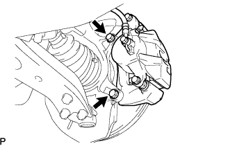
- Torque:
- 104 N*m{ 1,060 kgf*cm , 77 ft.*lbf }
| 12. INSTALL FRONT SPEED SENSOR |
Install the speed sensor to the steering knuckle with the bolt.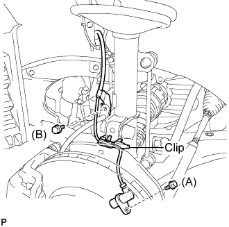
- Torque:
- Bolt A:
- 8.0 N*m{ 82 kgf*cm , 71 in.*lbf }
- NOTICE:
- Be careful not to damage the speed sensor.
- Prevent foreign matter from attaching to the speed sensor.
- Do not twist the sensor wire when installing the speed sensor.
- Be careful not to damage the speed sensor.
Install the flexible hose and the speed sensor to the shock absorber with the bolt and set the clip of sensor on the knuckle.
- Torque:
- Bolt B:
- 19 N*m{ 192 kgf*cm , 14 ft.*lbf }
| 13. INSTALL FRONT AXLE HUB NUT |
Using a socket wrench (30 mm), install a new axle hub nut.
- Torque:
- 294 N*m{ 3,000 kgf*cm , 217 ft.*lbf }
- NOTICE:
- Stake the nut after inspecting for looseness and runout in the following steps.
| 14. SEPARATE FRONT DISC BRAKE CALIPER ASSEMBLY |
Remove the 2 bolts, and separate the front disc brake caliper assembly.
- NOTICE:
- Use a wire or an equivalent to keep the brake caliper from hanging down by the flexible hose.
| 15. REMOVE FRONT DISC |
| 16. INSPECT FRONT AXLE HUB BEARING LOOSENESS |
Using a dial indicator, check for looseness near the center of the axle hub.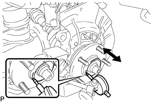
- Maximum:
- 0.05 mm (0.0020 in.)
- NOTICE:
- Ensure that the dial indicator is set at right angles to the measurement surface.
- HINT:
- If looseness exceeds the maximum, replace the bearing.
| 17. INSPECT FRONT AXLE HUB RUNOUT |
Using a dial indicator, check for runout on the surface of the axle hub outside the hub bolt.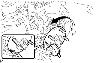
- Maximum:
- 0.05 mm (0.0020 in.)
- NOTICE:
- Ensure that the dial indicator is set at right angles to the measurement surface.
- HINT:
- If runout exceeds the maximum, replace the axle hub.
| 18. INSTALL FRONT DISC |
| 19. INSTALL FRONT DISC BRAKE CALIPER ASSEMBLY |
Install the front disc brake caliper assembly with the 2 bolts to the steering knuckle.
- Torque:
- 104 N*m{ 1,060 kgf*cm , 77 ft.*lbf }
| 20. INSTALL FRONT AXLE HUB NUT |
Using a chisel and hammer, stake the axle hub nut.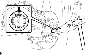
| 21. CHECK ABS SPEED SENSOR SIGNAL |
| 22. INSTALL FRONT WHEEL |
- Torque:
- 103 N*m{ 1,050 kgf*cm , 76 ft.*lbf }
| 23. INSPECT AND ADJUST FRONT WHEEL ALIGNMENT |