REMOVAL
Removal / installation
| 1. REMOVE DECK BOARD SUB-ASSEMBLY |

Disengage the 5 clips and turn up the front side of the deck board.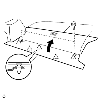

Remove the 2 bolts and deck board sub-assembly.
| 2. REMOVE FRONT DECK FLOOR BOX |
Using a clip remover, remove the 2 clips and deck floor box front.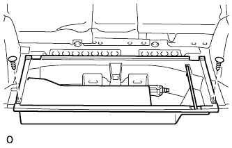
| 3. REMOVE REAR DECK FLOOR BOX |
Using a clip remover, remove the 2 clips and deck floor box rear.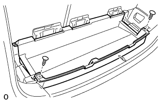
| 4. REMOVE DECK NO.2 BOARD SUB-ASSEMBLY |
Remove the 4 blots, 2 nuts and deck No.2 board sub-assembly.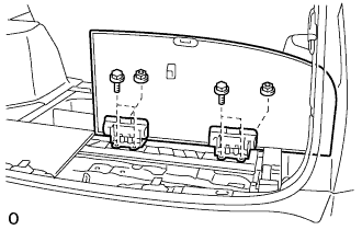
| 5. REMOVE DECK NO.3 BOARD SUB-ASSEMBLY |
Remove the 2 bolts, 2 nuts and deck No.3 board sub-assembly.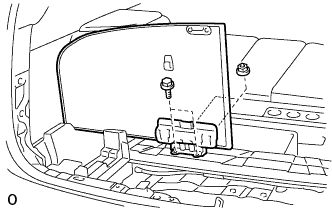
| 6. REMOVE REAR FLOOR FINISH PLATE |
Using a clip remover, remove the 2 clips.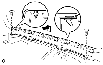
Disengage the 2 claws and 6 clips, and remove the rear floor finish plate.
| 7. REMOVE JACK CARRIER SUPPORT |
| 8. REMOVE JACK ASSEMBLY |
| 9. REMOVE JACK CARRIER ASSEMBLY |
| 10. REMOVE DECK SIDE TRIM BOX RH |
| 11. REMOVE DECK SIDE TRIM BOX LH |
Remove the clip (A).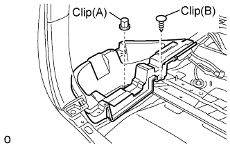
Using a clip remover, remove the clip (B) and deck side trim box.
| 12. REMOVE REAR DOOR SCUFF PLATE |
Disengage the 4 claws and 2 clips, and remove the rear door scuff plate.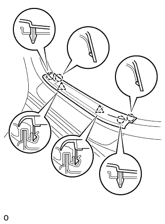
Disconnect the connector. (w/ illumination scuff plate)
| 13. REMOVE DECK SIDE TRIM COVER |
Using a moulding remover, disengage 3 claws (A).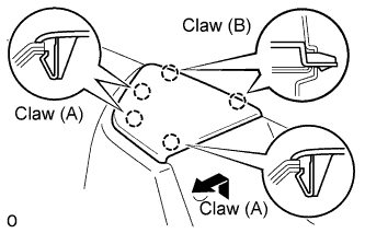
Disengage 2 claws (B) and remove the deck side trim cover by pulling it to inside the vehicle.
| 14. REMOVE REAR SEAT SIDE COVER |
Using a clip remover, remove the 3 clips.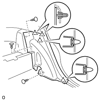
Disengage the 4 clips and remove the rear seat side cover.
| 15. REMOVE REAR FLOOR FINISH SIDE PLATE |
Using a clip remover, remove the clip.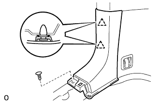
Disengage the 2 clips and remove the rear floor finish side plate.
| 16. REMOVE DECK TRIM SIDE PANEL ASSEMBLY |
Using a clip remover, remove the 4 clips.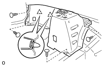
Disengage the 2 clips and remove the deck trim side panel assembly.
| 17. REMOVE REAR WHEEL |
| 18. SEPARATE REAR STABILIZER LINK ASSEMBLY |
Support the rear axle carrier with a jack using a wooden block to avoid damage.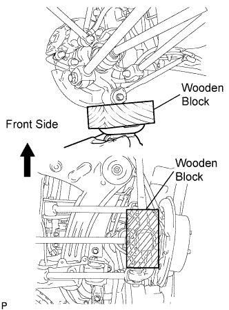
Remove the nut and separate the rear stabilizer link assembly from the rear shock absorber.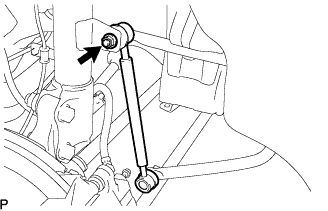
- HINT:
- If the ball joint turns together with the nut, use a hexagon wrench (5 mm) to hold the stud.
| 19. SEPARATE REAR SPEED SENSOR |
Remove the 3 bolts, and disconnect the rear brake flexible hose and rear speed sensor from the rear shock absorber with coil spring and rear axle carrier.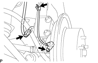
- NOTICE:
- Be sure to remove the rear speed sensor from the rear shock absorber with coil spring.
| 20. REMOVE REAR SHOCK ABSORBER WITH COIL SPRING |
Loosen the lock nut of the rear shock absorber with coil spring.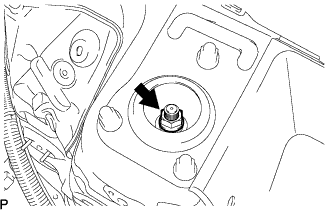
- NOTICE:
- Do not remove the lock nut.
- Only loosen the nut when disassembling the rear shock absorber with coil spring.
- Do not remove the lock nut.
Remove the 2 nuts and bolt on the lower side of the rear shock absorber with coil spring.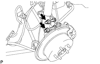
- NOTICE:
- When removing the nuts, keep the bolts from rotating.
- Keep one bolt inserted to secure the hub and disc rotor.
- When removing the nuts, keep the bolts from rotating.
Remove the 3 nuts on the upper side of the rear shock absorber with coil spring.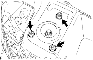
Lower the rear axle carrier, and remove the 2 bolts on the lower side of the rear shock absorber with coil spring.
- NOTICE:
- Make sure that the rear speed sensor is disconnected from the rear shock absorber with coil spring.