Illumination Circuit
Circuit diagnosis
DESCRIPTION
Power is supplied to the multi-display switch illumination when the light control switch is in the TAIL or HEAD position.WIRING DIAGRAM
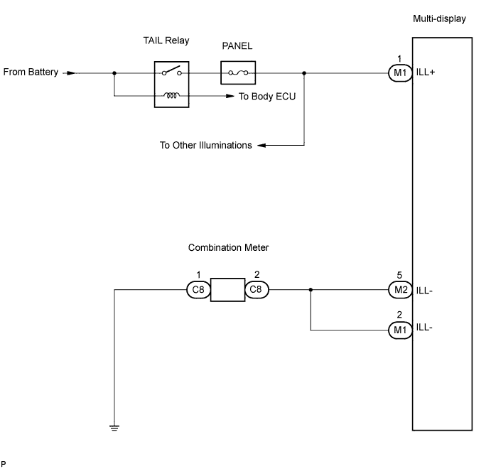

INSPECTION PROCEDURE
| 1. CHECK ILLUMINATION |

Check if the illumination for the multi-display, radio receiver, headlight cleaner switch, glove box or others (seat heater switch, cigarette lighter, etc.) comes on when the light control switch is turned to the HEAD or TAIL position.
- RESULT:
Condition
Proceed to
Illumination comes on for components except multi-display
A
Illumination comes on only for glove box and steering pad switch
B
No illumination comes on (multi-display, glove box, cigarette lighter, etc.)
C
|
|
||||
|
|
||||


| A | |
 |
| 2. INSPECT MULTI-DISPLAY |
Disconnect the multi-display connector M1.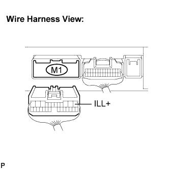
Measure the voltage according to the value(s) in the table below.
- Voltage:
Tester connection
Condition
Specified condition
ILL+ - Body ground
Light control SW HEAD or TAIL
10 to 14 V
|
|
||||
| OK | |
|
| 3. CHECK HARNESS AND CONNECTOR (MULTI-DISPLAY - COMBINATION METER) |
Disconnect the multi-display connectors M1 and M2 and combination meter connector C8.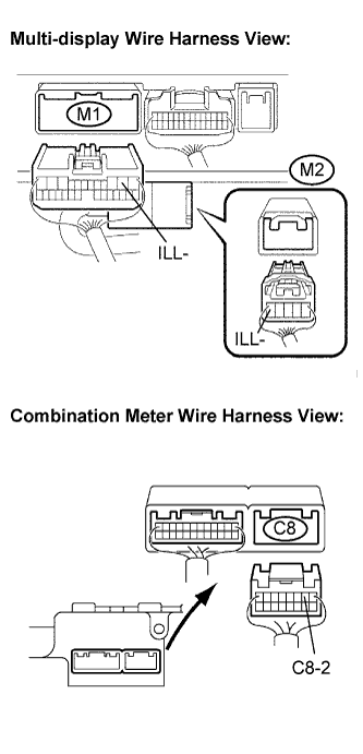
Measure the resistance according to the value(s) in the table below.
- Resistance:
Tester connection
Condition
Specified condition
ILL- (M1-2) - C8-2
Always
Below 1 Ω
ILL- (M2-5) - C8-2
Always
Below 1 Ω
ILL- (M1-2) - Body ground
Always
10 kΩ or higher
ILL- (M2-5) - Body ground
Always
10 kΩ or higher
|
|
||||
| OK | ||
 |
||
| ||
| 4. CHECK HARNESS AND CONNECTOR (MULTI-DISPLAY - COMBINATION METER) |
Disconnect the multi-display connectors M1 and M2 and combination meter connector C8.
Measure the resistance according to the value(s) in the table below.
- Resistance:
Tester connection
Condition
Specified condition
ILL- (M1-2) - C8-2
Always
Below 1 Ω
ILL- (M2-5) - C8-2
Always
Below 1 Ω
ILL- (M1-2) - Body ground
Always
10 kΩ or higher
ILL- (M2-5) - Body ground
Always
10 kΩ or higher
|
|
||||
| OK | ||
|
||
| ||