Dimmer Signal Circuit
Circuit diagnosis
DESCRIPTION
The multi-display dims the display and panel switches by receiving a TAIL cancel signal from the body ECU.WIRING DIAGRAM
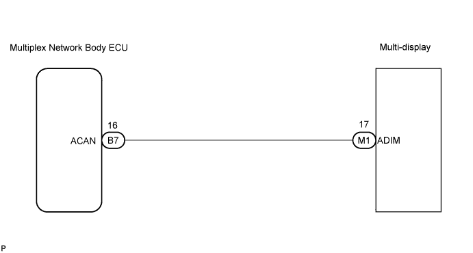

INSPECTION PROCEDURE
| 1. CHECK HARNESS AND CONNECTOR (MULTIPLEX NETWORK BODY ECU - MULTI-DISPLAY) |

Disconnect the multiplex network body ECU connector B7 and multi-display connector M1.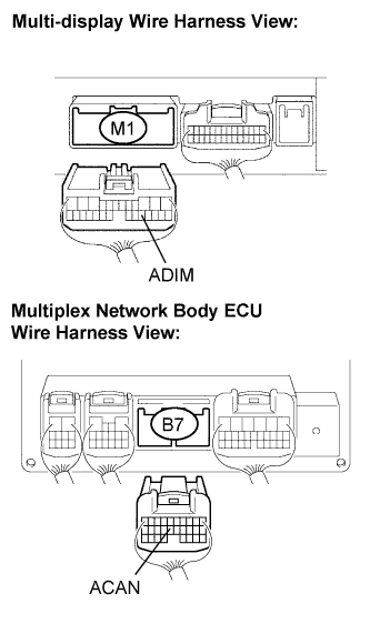
Measure the resistance according to the value(s) in the table below.
- Resistance:
Tester connection
Condition
Specified condition
ADIM - ACAN
Always
Below 1 Ω
ADIM - Body ground
Always
10 kΩ or higher
|
|
||||

| OK | |
 |
| 2. INSPECT MULTIPLEX NETWORK BODY ECU |
Reconnect the multiplex network body ECU connector.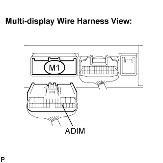
Turn the ignition switch to the ON position.
Turn the light control switch to the TAIL or HEAD position.
Measure the voltage according to the value(s) in the table below.
- Voltage:
Tester connection
Condition
Specified condition
ADIM - Body ground
Automatic light control sensor is covered.
Above 9 V
|
|
||||
| OK | ||
 |
||
| ||