TERMINALS OF ECU
System information
| CHECK INSTRUMENT PANEL J/B ASSEMBLY (BODY ECU) |
Disconnect the B5 and B6 ECU connectors.
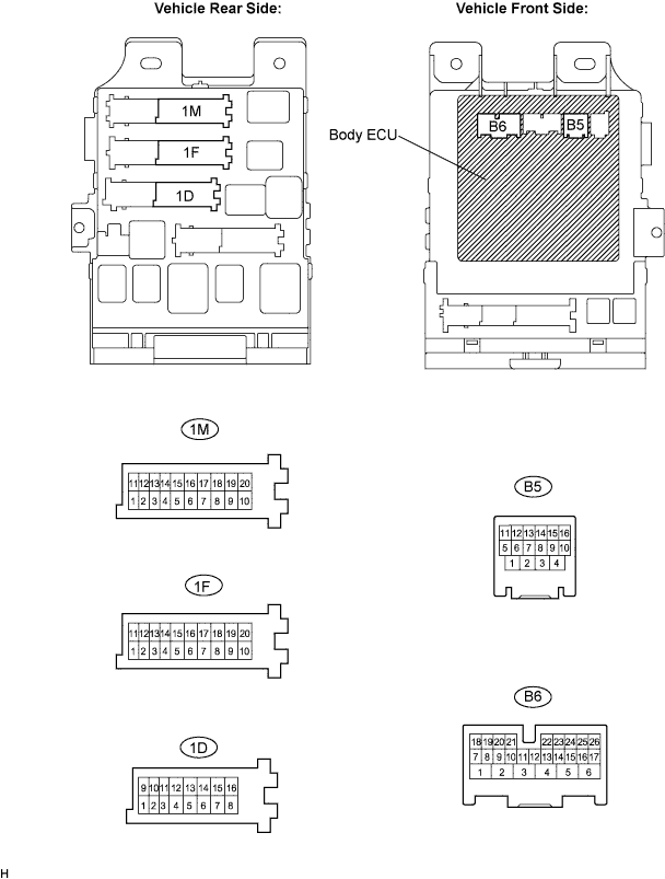

Disconnect the 1D, 1F and 1M J/B connectors.
Measure the voltage and resistance according to the value(s) in the table below.
- Standard resistance:
Symbols
(Terminal No.)
Wiring Color
Terminal Description
Condition
Specified Condition
BECU (1D-10) - Body ground
W - Body ground
+B (BECU) power supply
Constant
10 to 14 V
GND1 (1F-10) - Body ground
W-B - Body ground
Ground
Constant
Below 1 Ω
GND2 (1M-9) - Body ground
W-B - Body ground
Ground
Constant
Below 1 Ω
DCTY (B5-14) - Body ground
L - Body ground
Driver door courtesy switch input
Driver door
CLOSED → OPEN
10 kΩ or higher →
Below 1 Ω
KSW (B6-21) - Body ground
B - Body ground
Key unlock warning switch input
No key in ignition key cylinder →
Key inserted
10 kΩ or higher →
Below 1 Ω
- HINT:
- If the result is not as specified, there may be a malfunction on the wire harness side.
Reconnect the 1D, 1F, 1M, B5 and B6 connectors.
Measure the voltage according to the value(s) in the table below.
- Standard voltage:
Symbols
(Terminal No.)
Wiring Color
Terminal Description
Condition
Specified Condition
DCTY(B5-14) - Body ground
L - Body ground
Driver door courtesy switch input
Driver door
CLOSED → OPEN
10 to 14 → 0V