REMOVAL
Removal / installation
| 1. PRECAUTION |

| 2. PLACE FRONT WHEELS FACING STRAIGHT AHEAD |
| 3. DISCONNECT CABLE FROM NEGATIVE BATTERY TERMINAL |
- NOTICE:
- Start the overhaul of the steering column assembly at least 90 seconds after disconnecting the negative cable from the battery.
- Be sure to disconnect the negative cable of the battery properly so that the following procedure can be performed without any problem.
- Start the overhaul of the steering column assembly at least 90 seconds after disconnecting the negative cable from the battery.
With the ignition key in the key cylinder and the ignition switch ON, perform tilt-down and telescoping operation by adjusting the tilt and telescopic switch.
Disconnect the negative cable of the battery with the ignition key in the key cylinder.
Remove the ignition key from the key cylinder.
| 4. REMOVE FRONT WHEEL LH |
| 5. REMOVE FRONT DOOR SCUFF PLATE LH |
Disengage the 6 claws and 4 clips, and remove the front door scuff plate.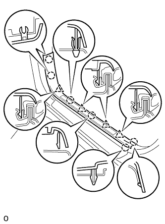

Disconnect the connector. (w/ illumination scuff plate)
| 6. REMOVE COWL SIDE TRIM SUB-ASSEMBLY LH |
Remove the 2 clips and the cowl side trim sub-assembly LH.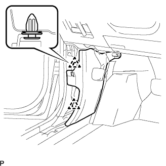
| 7. REMOVE INSTRUMENT PANEL FINISH PANEL SUB-ASSEMBLY LOWER |
Using a screwdriver, open the instrument panel finish panel sub-assembly lower cover.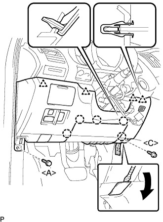
- HINT:
- Tape the screwdriver tip before use.
Remove the bolt <A> and the screw <C>.
Disconnect the hood lock control cable assembly.
Disengage the 5 claws and the 4 clips.
Disconnect the connectors and then remove the instrument panel finish panel sub-assembly lower.
| 8. REMOVE INSTRUMENT PANEL AIRBAG ASSEMBLY LOWER NO.1 |
Disconnect the connector from the driver side knee airbag assembly.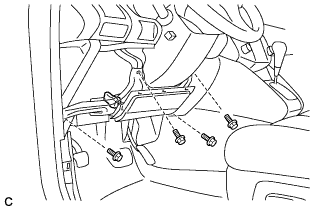
- NOTICE:
- When handling the airbag connector, take care not to damage the airbag wire harness.
Remove the 4 bolts and the driver side knee airbag assembly.
| 9. REMOVE STEERING WHEEL COVER LOWER NO.3 |
Using a screwdriver, remove the steering wheel No.3 cover lower.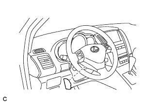
- HINT:
- Tape up the screwdriver tip before use.
| 10. REMOVE STEERING WHEEL COVER LOWER NO.2 |
Using a screwdriver, remove the steering wheel No.2 cover lower.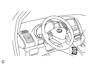
- HINT:
- Tape up the screwdriver tip before use.
| 11. REMOVE STEERING PAD ASSEMBLY |
Using a "torx" socket wrench (T30), loosen the 2 "torx" screws until the groove along the screw circumference catches on the screw case.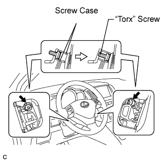
Pull out the steering pad from the steering wheel assembly and support the steering pad with one hand as shown in the illustration.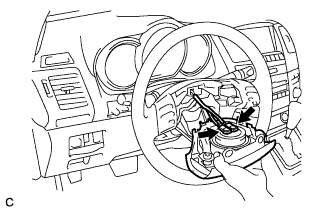
- NOTICE:
- When removing the steering pad, do not pull the airbag wire harness.
Disconnect the horn connector.
Disconnect the 2 connectors from the steering pad.
- NOTICE:
- When handling the airbag connector, take care not to damage the airbag wire harness.
Remove the steering pad.
| 12. REMOVE STEERING WHEEL ASSEMBLY |
Remove the steering wheel assembly set nut.
Put matchmarks on the steering wheel assembly and main shaft assembly.
Using SST, remove the steering wheel assembly.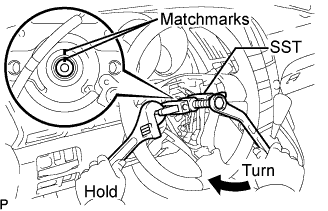
- SST
- 09950-50013
(09951-05010, 09952-05010, 09953-05020, 09954-05031)
| 13. REMOVE STEERING COLUMN COVER |
Remove the 3 screws.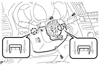
Disengage the 2 claws and remove the steering column cover lower.
- NOTICE:
- Do not damage the tilt and telescopic switch.
Disengage the claw and remove the steering column cover upper.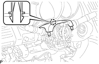
| 14. REMOVE TILT AND TELESCOPIC SWITCH |
Disconnect the connector.
Using a screwdriver, disengage the claw and pull out the tilt and telescopic switch.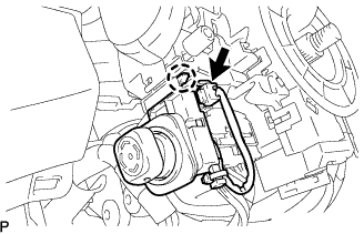
- NOTICE:
- Pushing on the claw too hard will break the claw.
- HINT:
- Tape the screwdriver tip before use.
| 15. REMOVE TURN SIGNAL SWITCH ASSEMBLY WITH SPIRAL CABLE SUB-ASSEMBLY |
Disconnect the connectors from the turn signal switch assembly with spiral cable sub-assembly.
Using pliers, grip the claws of the clip and remove the turn signal switch assembly with spiral cable sub-assembly from the steering column assembly.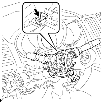
| 16. REMOVE AIR DUCT NO.1 |
Remove the bolt.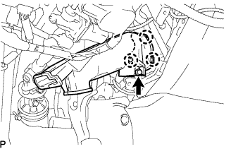
Disengage the 3 claws and remove the air duct No.1.
| 17. SEPARATE STEERING INTERMEDIATE SHAFT SUB-ASSEMBLY |
Loosen the bolt (A) and remove the clamp from the steering column hole shield.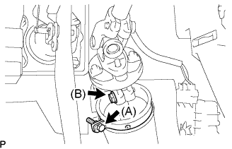
Loosen the bolt (B)
- HINT:
- Do not remove the bolt (B).
Remove the bolt, and then slide the steering intermediate shaft sub-assembly.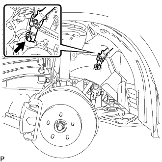
- NOTICE:
- Do not separate the steering intermediate shaft sub-assembly.
Put matchmarks on the steering intermediate shaft sub-assembly and the power steering link assembly.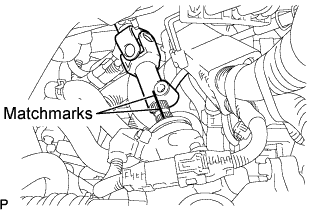
Separate the steering intermediate shaft sub-assembly from the power steering link assembly.
| 18. REMOVE INSTRUMENT PANEL FINISH PLATE |
| 19. REMOVE STEERING COLUMN ASSEMBLY |
Disconnect the connectors and wire harness clamps from the steering column assembly.
Remove the 2 bolts, 2 nuts and the steering column assembly.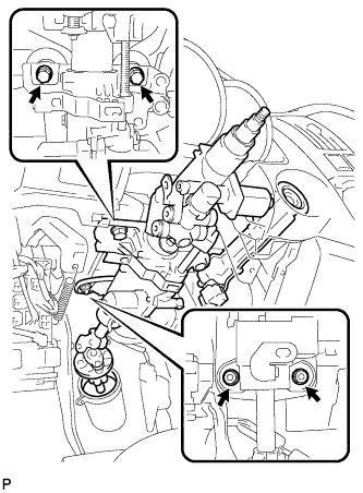
| 20. REMOVE STEERING INTERMEDIATE SHAFT SUB-ASSEMBLY |
Put matchmarks on the steering intermediate shaft sub-assembly and the steering shaft universal joint assembly.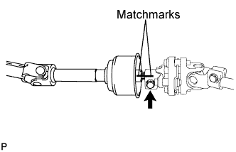
Remove the bolt and the steering intermediate shaft sub-assembly.
| 21. REMOVE STEERING COLUMN HOLE COVER SUB-ASSEMBLY NO.2 |
Remove steering column hole cover sub-assembly No.2 from the steering intermediate shaft sub-assembly.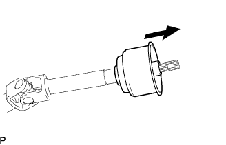
| 22. REMOVE STEERING SHAFT UNIVERSAL JOINT ASSEMBLY |
Put matchmarks on the steering shaft universal joint assembly and the steering column assembly.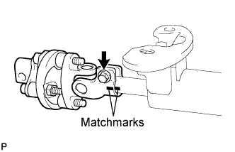
Remove the bolt and the steering shaft universal joint assembly.