TERMINALS OF ECU
System information
| CHECK POWER BACK DOOR ECU |
Disconnect the P10 and P11 connectors from power back door ECU.
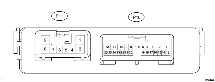

Measure the resistance according to the value(s) in the table below.
- Standard resistance:
Symbols
(Terminal No.)
Wiring Color
Terminal Description
Condition
Specified Condition
BDDN (P10-4) - Body ground
W - Body ground
Power back door closer switch signal input
Power back door closer switch
OFF → ON
10 kΩ or higher →
Below 1 Ω
MSE (P10-5) - MSW (P10-6)
W-B - G
Power back door main switch signal circuit
Power back door main switch
OFF → ON
10 kΩ or higher →
Below 1 Ω
CTYE (P10-7) - Body ground
P - Body ground
Back door courtesy switch signal input
Back door is closed → opened
10 kΩ or higher →
Below 1 Ω
OSL (P10-14) - OSE (P10-15)
G - Y
Power back door touch sensor LH circuit
Back door touch sensor LH not
pressed → pressed
Approx. 1 kΩ →
Below 100 Ω
OSR (P10-16) - OSE (P10-15)
L - Y
Power back door touch sensor RH circuit
Back door touch sensor RH not
pressed → pressed
Approx. 1 kΩ →
Below 100 Ω
CTYO (P10-19) - Body ground
BR - Body ground
Back door courtesy switch signal output
Back door is closed → opened
10 kΩ or higher →
Below 1 Ω
GND (P11-8) - Body ground
W-B - Body ground
Ground
Always
Below 1 Ω
- HINT:
- If the result is not as specified, there may be a malfunction on the wire harness side.
Measure the voltage according to the value(s) in the table below.
- Standard voltage:
Symbols
(Terminal No.)
Wiring Color
Terminal Description
Condition
Specified Condition
IG (P10-9) - Body ground
GR - Body ground
Ignition switch input
Ignition switch OFF → ON
Below 1 V →
10 to 14 V
ECUB (P10-10) - Body ground
BR - Body ground
ECU power supply
Always
10 to 14 V
MPX1 (P10-22) - Body ground
SB - Body ground
Multiplex communication signal circuit
Ignition switch ON
Signal waveform
B (P11-2) - Body ground
Y - Body ground
Motor drive power supply
Always
10 to 14 V
- HINT:
- If the result is not as specified, there may be a malfunction on the wire harness side.
Reconnect the P10 and P11 connectors to the back door ECU.
Measure the voltage according to the value(s) in the table below.
- Standard voltage:
Symbols
(Terminal No.)
Wiring Color
Terminal Description
Condition
Specified Condition
BZR- (P10-1) - BZR+ (P10-2)
O - B
Power back door warning buzzer signal input
Back door warning buzzer is
stopped → sounded
Below 1 V →
10 to 14 V
HAF (P10-8) - Body ground
R - Body ground
Back door lock half-latch switch signal input
Back door is opened →
back door closer motor is operated →
back door is closed
Below 1 V →
10 to 14 V →
Below 1 V
DC- (P10-11) - DC+ (P10-12)
B - G
Back door closer motor circuit
Back door closer motor is stopped → operated
Below 1 V →
10 to 14 V
FUL (P10-18) - Body ground
V - Body ground
Back door lock full-latch switch signal input
Back door is closed → opened
10 to 14 V →
Below 1 V
POS (P10-21) - Body ground
LG - Body ground
Back door lock position switch signal input
Back door is opened →
back door closer motor is operated →
back door is closed
Below 1 V →
10 to 14 V →
Below 1 V
DS2 (P10-24) - DSG (P10-23)
GR - R
Power back door drive unit pulse sensor 2 signal input circuit
Power back door motor is stopped → operated
Below 1 V →
Alternating between 10 to 14 V and below 1 V
DS1 (P10-25) - DSG (P10-23)
Y - R
Power back door drive unit pulse sensor 1 signal input circuit
Power back door motor is stopped → operated
Below 1 V →
Alternating between 10 to 14 V and below 1 V
DSV (P10-26) - DSG (P10-23)
L - R
Power back door drive unit pulse sensor power supply circuit
Always
10 to 14 V
BD+ (P11-1) - BD- (P11-3)
B - W
Power back door drive unit motor circuit
Power back door motor is stopped → operated
Below 1 V →
10 to 14 V
CL- (P11-6) - CL+ (P11-7)
G - BR
Power back door drive unit clutch circuit
Power back door motor is stopped → operated
Below 1 V →
10 to 14 V
- HINT:
- Use an oscilloscope to check the output voltages of the power back door main switch, buzzer and pulse sensor.
- If the result is not as specified, the ECU may have a malfunction.
- Use an oscilloscope to check the output voltages of the power back door main switch, buzzer and pulse sensor.
| CHECK INSTRUMENT PANEL JUNCTION BLOCK ASSEMBLY(BODY ECU) |
Disconnect the 1A, 1D, 1F, 1M and B7 connectors from the instrument panel junction block assembly and body ECU.
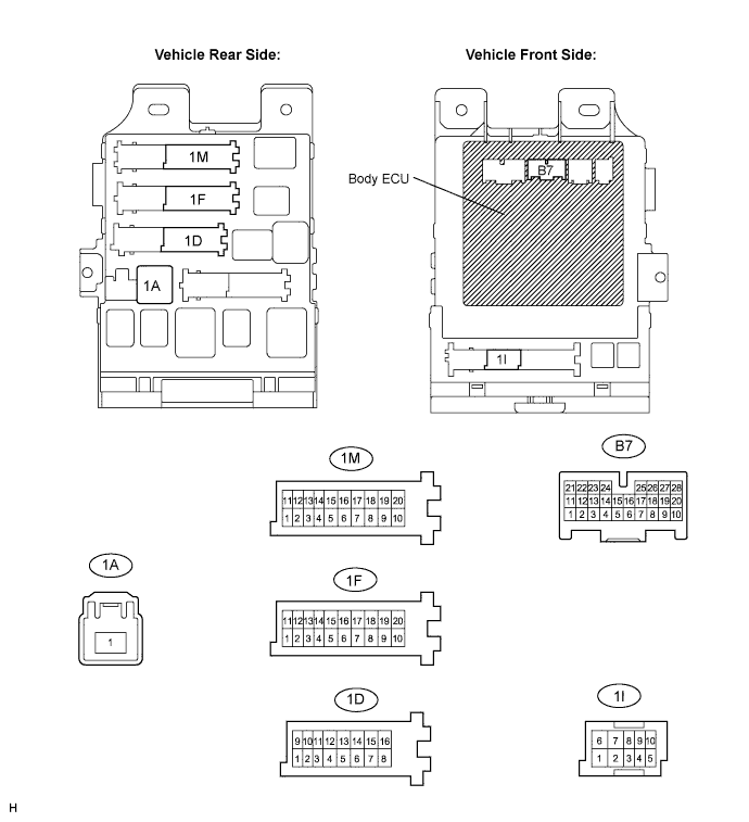
Measure the resistance according to the value(s) in the table below.
- Standard resistance:
Symbols
(Terminal No.)
Wiring Color
Terminal Description
Condition
Specified Condition
GND1 (1F-10) - Body ground
W-B - Body ground
Ground
Always
Below 1 Ω
GND2 (1M-9) - Body ground
W-B - Body ground
Ground
Always
Below 1 Ω
PBDS (B7-2) - Body ground
V - Body ground
Power back door opener/ closer switch signal input
Power back door opener/closer switch OFF → ON
10 kΩ or higher →
Below 1 Ω
BCTY (B7-25) - Body ground
P - Body ground
Back door courtesy light switch signal input
Back door is closed → opened
10 kΩ or higher →
Below 1 Ω
- HINT:
- If the result is not as specified, there may be a malfunction on the wire harness side.
Measure the voltage according to the value(s) in the table below.
- Standard voltage:
Symbols
(Terminal No.)
Wiring Color
Terminal Description
Condition
Specified Condition
BATB (1A-1) - Body ground
B - Body ground
+B (power system, battery system) power supply
Always
10 to 14 V
BECU (1D-10) - Body ground
W - Body ground
+B (BECU) power supply
Always
10 to 14 V
ALTB (1D-16) - Body ground
W - Body ground
+B (power system, generator system) power supply
Always
10 to 14 V
- HINT:
- If the result is not as specified, there may be a malfunction on the wire harness side.
Reconnect the 1A, 1D, 1F, 1M and B7 connectors to the instrument panel junction block assembly and body ECU.
Measure the voltage according to the value(s) in the table below.
- Standard voltage:
Symbols
(Terminal No.)
Wiring Color
Terminal Description
Condition
Specified Condition
IG (1I-4) - Body ground
O - Body ground
Ignition switch power supply
Ignition switch OFF → ON
10 to 14 V → Below 1 V
- HINT:
- If the result is not as specified, the instrument panel junction block assembly and body ECU may have a malfunction.