DISASSEMBLY
Removal / installation
| 1. REMOVE FRONT DOOR INSIDE HANDLE BEZEL PLUG |

Using a screwdriver wrapped with protective tape, disengage the 3 claws and remove the front door inside handle bezel plug.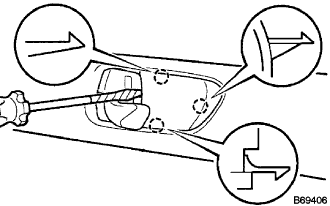

| 2. REMOVE POWER WINDOW REGULATOR MASTER SWITCH ASSEMBLY |
Using a screwdriver wrapped with protective tape, disengage the 2 claws and the 2 clips.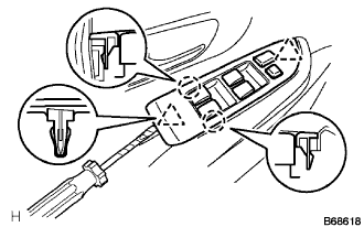
Disconnect the connector and remove the power window regulator master switch assembly.
| 3. REMOVE DOOR ARMREST COVER |
Remove the door armrest cover.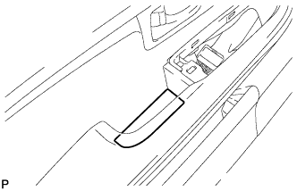
| 4. REMOVE FRONT DOOR LOWER FRAME BRACKET GARNISH |
Using a screwdriver wrapped with protective tape, disengage the 2 clips and claw, and remove the front door lower frame bracket garnish.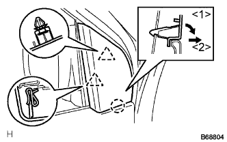
| 5. REMOVE FRONT DOOR TRIM BOARD SUB-ASSEMBLY |
Remove the 2 screws.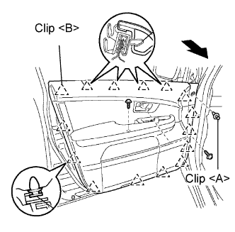
Remove the clip <A>.
Pulling the front door trim board sub-assembly in the direction of the arrow shown in the illustration, disengage the 15 clips <B>.
Disconnect the cables and each connector from the back side of the inside handle and the front door trim board sub-assembly, remove the front door trim board sub-assembly.
Disengage the 2 claws and remove the front door courtesy light.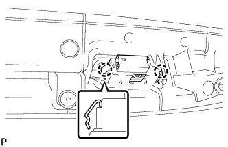
| 6. REMOVE FRONT DOOR GLASS WEATHERSTRIP INNER |
Remove the front door glass weatherstrip inner as shown in the illustration.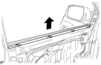
| 7. REMOVE FRONT DOOR ARMREST SET BRACKET |
Remove the 2 screws and the front door armrest set bracket.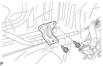
| 8. REMOVE FRONT NO.1 SPEAKER ASSEMBLY |
Disconnect the connector.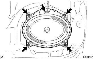
Remove the 4 bolts and the front No.1 speaker.
| 9. REMOVE OUTER REAR VIEW MIRROR ASSEMBLY |
Disconnect the connector and remove the clamp.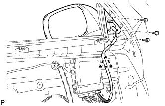
Remove the 3 bolts and the outer rear view mirror assembly.
| 10. REMOVE FRONT DOOR SERVICE HOLE COVER |
Disconnect each connector and remove the front door service hole cover.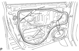
- HINT:
- Remove the remaining tape on the door side.
| 11. REMOVE FRONT DOOR GLASS RUN |
Connect the power window regulator master switch assembly.
Fully lower the front door glass sub-assembly.
Remove the front door glass run.
| 12. REMOVE FRONT DOOR GLASS SUB-ASSEMBLY |
Operate the power window regulator master switch assembly and move the front door glass sub-assembly so that the door glass bolts can be seen.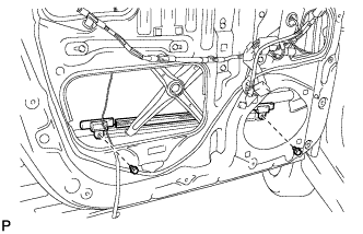
Remove the 2 bolts.
- NOTICE:
- After the bolts are removed, the door glass may fall and become deformed.
Remove the front door glass sub-assembly as shown in the illustration.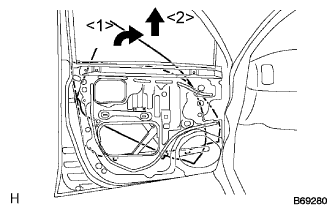
- NOTICE:
- Do not damage the door glass.
Disconnect the power window regulator master switch assembly.
| 13. REMOVE FRONT DOOR WINDOW REGULATOR SUB-ASSEMBLY |
Disconnect the connector.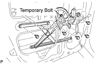
Loosen the temporary bolt.
- NOTICE:
- If the temporary bolt is removed, the front door window regulator may fall and become deformed.
Remove the 5 bolts and the front door window regulator sub-assembly and the power window regulator motor assembly front as a unit.
Remove the temporary bolt from the front door window regulator sub-assembly.
| 14. REMOVE POWER WINDOW REGULATOR MOTOR ASSEMBLY FRONT |
Using a "torx" driver (T25), remove the 3 screws and the power window regulator motor assembly front.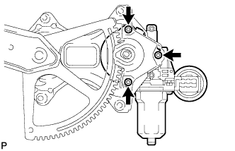
| 15. REMOVE FRONT DOOR FRAME SUB-ASSEMBLY REAR LOWER |
Remove the bolt and the front door frame sub-assembly rear lower as shown in the illustration.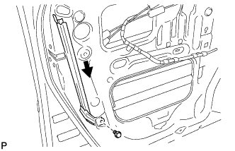
| 16. REMOVE FRONT DOOR LOCK ASSEMBLY |
Disconnect the connector.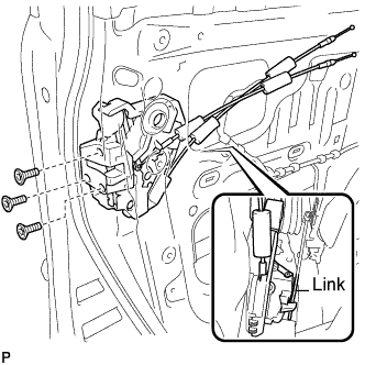
Using a "torx" socket wrench (T30), remove the 3 screws.
Slide the front door lock assembly downward, pull out the link from the outside handle frame, and remove the front door lock assembly and cables as a unit
| 17. REMOVE DOOR LOCK WIRING HARNESS SEAL |
| 18. REMOVE FRONT DOOR OUTSIDE HANDLE COVER |
Remove the hole plug.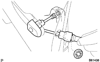
Using a "torx" socket wrench (T30), loosen the screw and remove the front door outside handle cover and the door lock key cylinder as a unit.
- HINT:
- Screw cannot be removed because it is integrated into the front door outside handle frame sub-assembly.
| 19. REMOVE FRONT DOOR HANDLE ASSEMBLY OUTSIDE |
Remove the front door handle assembly outside as shown in the illustration.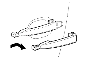
| 20. REMOVE FRONT DOOR OUTSIDE HANDLE PAD |
Disengage the 3 claws and remove the front door outside handle pad.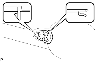
| 21. REMOVE FRONT DOOR OUTSIDE HANDLE PAD REAR |
Disengage the 2 claws and remove the front door outside handle pad rear.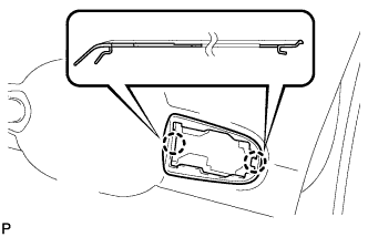
| 22. REMOVE FRONT DOOR OUTSIDE HANDLE FRAME SUB-ASSEMBLY |
Using a "torx" socket wrench (T30), loosen the screw.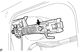
- HINT:
- Screw cannot be removed because it is integrated into the front door outside handle frame sub-assembly.
Disengage the claw and remove the front door outside handle frame sub-assembly.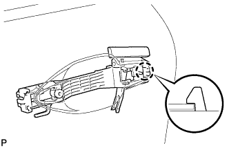
| 23. REMOVE FRONT DOOR CHECK COVER |
Disengage the pin and remove the front door check cover as shown in the illustration.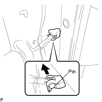
| 24. REMOVE FRONT DOOR CHECK ASSEMBLY |
Remove the bolt and 2 nuts, and the front door check assembly.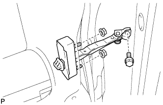
| 25. REMOVE FRONT DOOR WEATHERSTRIP |
Using the clip remover, remove the 3 clips and disengage the 18 clips and remove the front door weatherstrip.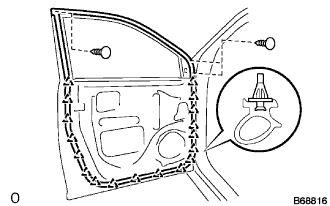
| 26. REMOVE FRONT DOOR BELT MOULDING ASSEMBLY |
Put protective tape under the moulding.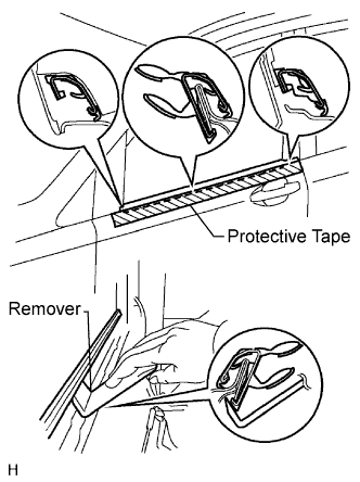
Using a moulding remover, disengage the claws and remove the front door belt moulding assembly.
- HINT:
- Tape the remover tip before use.
| 27. REMOVE FRONT DOOR WINDOW FRAME MOULDING REAR |
Remove the screw.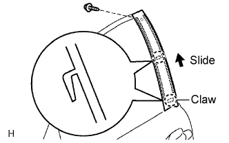
Using a heat light, heat the moulding.
- Heating temperature:
- 40 to 60°C (104 to 140°F)
- NOTICE:
- Do not heat the moulding excessively.
Slide the moulding upward to remove it.
- NOTICE:
- If reusing the moulding, take care not to damage the moulding.