B2222 Power back door does not operate
Diagnostic trouble codes
DESCRIPTION
- A pulse sensor is built into the power back door drive unit to detect foreign objects and back door position. The pulse sensor monitors the operating speed of the back door while the power back door is in operation to detect foreign objects. The pulse sensor also monitors where the back door is to detect the back door position. If a pulse signal that is out of the normal range is output, the power back door ECU will set DTC B2222.
- If DTC B2222 is set, the power back door system will be turned off. Thus, the back door will be switched to manual operation mode (not electrically controlled) and can be moved freely.
- In order to restore the power back door system to normal operation mode, first solve the problem indicated by DTC B2222 and then manually close the back door fully (reset operation).
- NOTICE:
- The power back door ECU records the back door positions in the memory. In the case where any of the batteries, fuses, power back door ECU and power back door drive unit are removed and then reinstalled, the power back door ECU loses the memory of the door positions. In such a case, resetting the power back door system is necessary. Refer to the resetting operation specified in page Click here.
DTC No.
DTC Detection Condition
Trouble Area
B2222
Power back door does not operate
- Wire harness
- Power back door drive unit
- Power back door ECU
WIRING DIAGRAM
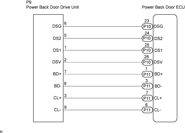

INSPECTION PROCEDURE
| 1. CHECK WIRE HARNESS (POWER BACK DOOR DRIVE UNIT - POWER BACK DDOR ECU) |

Disconnect the P9 unit and P10 ECU connectors.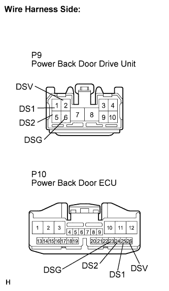
Measure the resistance according to the value(s) in the table below.
- Standard resistance:
Tester Connection
Specified Condition
P9-2 (DSV) - P10-26 (DSV)
Below 1 Ω
P9-6 (DSG) - P10-23 (DSG)
Below 1 Ω
P9-1 (DS1) - P10-25 (DS1)
Below 1 Ω
P9-5 (DS2) - P10-24 (DS2)
Below 1 Ω
|
|
||||

| OK | |
 |
| 2. INSPECT POWER BACK DOOR DRIVE UNIT ASSEMBLY |
Remove the unit.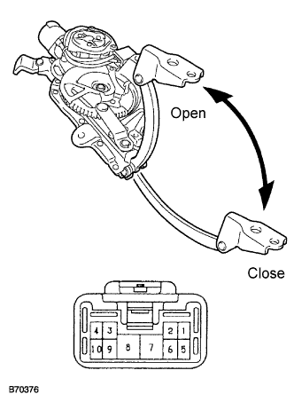
Connect the battery positive (+) lead to terminal 3 and battery negative (-) terminal lead to terminal 9.
Apply battery voltage to the terminals and check the motor operation.
- OK:
Measurement Condition
Specified Condition
Battery positive (+) → Terminal 7
Battery negative (-) → Terminal 8
Open
Battery positive (+) → Terminal 8
Battery negative (-) → Terminal 7
Close
Measure the resistance according to the value(s) in the table below.
- Standard resistance:
Tester Connection
Specified Condition
3 - 9
4.0 Ω
Reinstall the unit and connect the connector.
Using an oscilloscope, check the pulse generated when the door is manually opened and closed.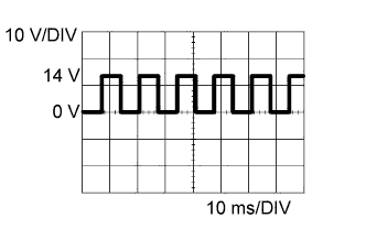
OK Terminal
1 - 6, 5 - 6
Tool setting
10 V/DIV., 10 ms/DIV.
Vehicle condition
Door moving
- HINT:
- A cycle of the pulse changes between approx. 10 to 20 msec. according to the speeds that the back door is moving.
|
|
||||
| OK | ||
 |
||
| ||