TERMINALS OF ECU
System information
| INSTRUMENT PANEL JUNCTION BLOCK ASSEMBLY (BODY ECU) |
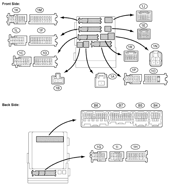

| Symbols (Terminal No.) |
Wiring Color |
Terminal Description |
Condition |
Specified Condition |
| ACC, IG (1A-1) - GND1 (1F-10) |
B - W-B |
Battery (Power source circuit) |
Always |
10 to 14 V |
| HRLY (1D-3) - GND1 (1F-10) |
GR - W-B |
HEAD Relay (HEAD signal) |
Light control switch is OFF or TAIL |
10 to 14 V |
| HRLY (1D-3) - GND1 (1F-10) |
GR - W-B |
HEAD Relay (HEAD signal) |
Light control switch is HEAD |
Below 1 V |
| DRL (1D-9) - GND1 (1F-10) |
P - W-B |
DIM Relay High beam signal) |
Headlight high beam is ON |
Below 1 V |
| DRL (1D-9) - GND1 (1F-10) |
P - W-B |
DIM Relay High beam signal) |
Headlight high beam is OFF |
10 to 14 V |
| BECU (1D-10) - GND1 (1F-10) |
W - W-B |
Battery (B+ circuit) |
Always |
10 to 14 V |
| ALTB (1D-16) - GND1 (1F-10) |
R-Y - W-B |
Battery |
Always |
10 to 14 V |
| MPX1 (1E-7) - GND1 (1F-10) |
BR - W-B |
Multiplex communication |
Ignition switch is OFF |
Below 1 V |
| MPX1 (1E-7) - GND1 (1F-10) |
BR - W-B |
Multiplex communication |
Ignition switch is ON |
Signal waveform |
| BECU (1F-1) - GND1 (1F-10) |
SB - W-B |
Overhead ECU (B+ circuit) |
Always |
10 to 14 V |
| GND1 (1F-10) - Body ground |
W-B - Body ground |
Body ground |
Always |
Below 1 V |
| TRLY (1H-11) - GND1 (1F-10) |
Y - W-B |
TAIL relay (TAIL signal) |
Light control switch is OFF |
Below 1 V |
| TRLY (1H-11) - GND1 (1F-10) |
Y - W-B |
TAIL relay (TAIL signal) |
Light control switch is TAIL and fog light switch is ON |
10 to 14 V |
| HRLY (1H-13) - GND1 (1F-10) |
R - W-B |
Headlight cleaner switch (HEAD signal) |
Light control switch is OFF or TAIL |
10 to 14 V |
| HRLY (1H-13) - GND1 (1F-10) |
R - W-B |
Headlight cleaner switch (HEAD signal) |
Light control switch is HEAD |
Below 1 V |
| ILE (1I-10) - GND1 (1F-10) |
R - W-B |
Key cylinder light (Illumination signal) |
Ignition key cylinder light is OFF |
10 to 14 V |
| ILE (1I-10) - GND1 (1F-10) |
R - W-B |
Key cylinder light (Illumination signal) |
Ignition key cylinder light is ON |
Below 1 V |
| TRLY (1L-3) - GND1 (1F-10) |
Y - W-B |
TAIL relay (TAIL signal) |
Light control switch is OFF |
Below 1 V |
| TRLY (1L-3) - GND1 (1F-10) |
Y - W-B |
TAIL relay (TAIL signal) |
Light control switch is TAIL and fog light switch is ON |
10 to 14 V |
| ILE (1M-1) - GND1 (1F-10) |
R - W-B |
Scuff plate illumination (Illumination signal) |
Scuff plate illumination OFF |
10 to 14 V |
| ILE (1M-1) - GND1 (1F-10) |
R - W-B |
Scuff plate illumination (Illumination signal) |
Scuff plate illumination ON |
Below 1 V |
| GND2 (1M-9) - GND1 (1F-10) |
W-B - W-B |
Body ground |
Always |
Below 1 V |
| HU (1N-2) - GND1 (1F-10) |
G - W-B |
Headlight dimmer switch (HIGH signal) |
Headlight dimmer switch is LOW |
10 to 14 V |
| HU (1N-2) - GND1 (1F-10) |
G - W-B |
Headlight dimmer switch (HIGH signal) |
Headlight dimmer switch is HIGH |
Below 1 V |
| LCTY (1O-7) - GND1 (1F-10) |
B - W-B |
Courtesy switch (Rear left door circuit) |
Rear left door is open |
Below 1 V |
| LCTY (1O-7) - GND1 (1F-10) |
B - W-B |
Courtesy switch (Rear left door circuit) |
Rear left door is closed |
Pulse generation (*1) |
| LSWL (1P-5) - GND1 (1F-10) |
GR - W-B |
Door lock position switch (Rear left door circuit) |
Rear left door is in unlock position |
Below 1 V |
| LSWL (1P-5) - GND1 (1F-10) |
GR - W-B |
Door lock position switch (Rear left door circuit) |
Rear left door is in lock position |
Pulse generation (*1) |
| ILE (1R-5) - GND1 (1F-10) |
SB - W-B |
Front interior illumination (Illumination signal) |
Front interior light is OFF |
10 to 14 V |
| ILE (1R-5) - GND1 (1F-10) |
SB - W-B |
Front interior illumination (Illumination signal) |
Front interior light is ON |
Below 1 V |
| MPX1 (1E-7) - GND1 (1F-10) |
BR - W-B |
Multiplex communication signal |
Ignition switch is OFF |
Below 1 V |
| MPX1 (1E-7) - GND1 (1F-10) |
BR - W-B |
Multiplex communication signal |
Ignition switch is ON |
Signal waveform |
| HDLO (B4-4) - GND1 (1F-10) |
SB - W-B |
Headlight cleaner relay (DRL signal) |
Ignition switch is ON and engine is running |
10 to 14 V |
| HDLO (B4-4) - GND1 (1F-10) |
SB - W-B |
Headlight cleaner relay (DRL signal) |
Ignition switch is OFF |
Below 1 V |
| FFGO (B4-7) - GND1 (1F-10) |
LG - W-B |
Front fog relay (Front fog circuit) |
Front fog light is OFF |
Below 1 V |
| FFGO (B4-7) - GND1 (1F-10) |
LG - W-B |
Front fog relay (Front fog circuit) |
Front fog light is ON |
10 to 14 V |
| DCYL (B5-13) - GND1 (1F-10) |
SB - W-B |
Courtesy light (Front left door circuit) |
Front left courtesy light is OFF |
10 to 14 V |
| DCYL (B5-13) - GND1 (1F-10) |
SB - W-B |
Courtesy light (Front left door circuit) |
Front left courtesy light N |
Below 1V |
| DCTY (B5-14) - GND1 (1F-10) |
L - W-B |
Courtesy switch (Front left door circuit) |
Front left door is open |
Below 1 V |
| DCTY (B5-14) - GND1 (1F-10) |
L - W-B |
Courtesy switch (Front left door circuit) |
Front left door is closed |
10 to 14 V |
| RCTY (B5-16) - GND1 (1F-10) |
GR - W-B |
Courtesy switch (Rear right door circuit) |
Rear right door is open |
Below 1 V |
| RCTY (B5-16) - GND1 (1F-10) |
GR - W-B |
Courtesy switch (Rear right door circuit) |
Rear right door is closed |
Pulse generation (*1) |
| CLTE (B6-4) - GND1 (1F-10) |
LG - W-B |
Automatic light control sensor (Ground circuit) |
Always |
Below 1 V |
| CLTS (B6-5) - GND1 (1F-10) |
B - W-B |
Automatic light control sensor (Signal circuit) |
Ignition switch is ON |
Below 1 V |
| CLTS (B6-5) - GND1 (1F-10) |
B - W-B |
Automatic light control sensor (Signal circuit) |
Ignition switch is OFF |
10 to 14 V |
| CLTB (B6-6) - GND1 (1F-10) |
P - W-B |
Automatic light control sensor (Power source circuit) |
Ignition switch is OFF |
10 to 14 V |
| CLTB (B6-6) - GND1 (1F-10) |
P - W-B |
Automatic light control sensor (Power source circuit) |
Ignition switch is ON |
Below 1 V |
| RFOG (B6-13) - GND (1F-10) |
SB - W-B |
Rear fog relay |
Rear fog light switch is OFF |
10 to 14 V |
| RFOG (B6-13) - GND (1F-10) |
SB - W-B |
Rear fog relay |
Rear fog light switch is ON |
Below 1 V |
| HF (B6-15) - GND1 (1F-10) |
Y - W-B |
Headlight dimmer switch (FLASH signal) |
Headlight dimmer switch is OFF |
10 to 14 V |
| HF (B6-15) - GND1 (1F-10) |
Y - W-B |
Headlight dimmer switch (FLASH signal) |
Headlight dimmer switch is FLASH |
Below 1 V |
| A (B6-16) - GND1 (1F-10) |
BR - W-B |
Light control switch (AUTO signal) |
Light control switch is OFF |
10 to 14 V |
| A (B6-16) - GND1 (1F-10) |
BR - W-B |
Light control switch (AUTO signal) |
Light control switch is AUTO |
Below 1 V |
| TAIL (B6-17) - GND1 (1F-10) |
O - W-B |
Light control switch (TAIL signal) |
Light control switch is OFF |
10 to 14 V |
| TAIL (B6-17) - GND1 (1F-10) |
O - W-B |
Light control switch (TAIL signal) |
Light control switch is TAIL |
Below 1 V |
| FFOG (B6-22) - GND1(1F-10) |
P - W-B |
Front fog light switch (Front fog light signal) |
Fog light switch is OFF |
10 to 14 V |
| FFOG (B6-22) - GND1(1F-10) |
P - W-B |
Front fog light switch (Front fog light signal) |
Fog light switch is ON |
Below 1 V |
| HEAD (B6-23) - GND1 (1F-10) |
V - W-B |
Light control switch (HEAD signal) |
Light control switch is OFF |
Below 1 V |
| HEAD (B6-23) - GND1 (1F-10) |
V - W-B |
Light control switch (HEAD signal) |
Light control switch is HEAD |
10 to 14 V |
| LSWR (B7-5) - GND1 (1F-10) |
B - W-B |
Door lock position switch (Rear right door circuit) |
Rear right door is in unlock position |
Below 1 V |
| LSWR (B7-5) - GND1 (1F-10) |
B - W-B |
Door lock position switch (Rear right door circuit) |
Rear right door is in lock position |
Pulse generation (*1) |
| PANL (B7-8) - GND1 (1F-10) |
GR - W-B |
Panel relay (Center console illumination) |
Instrument panel illumination is OFF |
10 to 14 V |
| PANL (B7-8) - GND1 (1F-10) |
GR - W-B |
Panel relay (Center console illumination) |
Instrument panel illumination is ON |
Below 1 V |
| RFGO (B7-9) - GND1 (1F-10) |
R - W-B |
Rear fog relay (Rear fog circuit) |
Rear fog light is OFF |
10 to 14 V |
| RFGO (B7-9) - GND1 (1F-10) |
R - W-B |
Rear fog relay (Rear fog circuit) |
Rear fog light is ON |
Below 1 V |
| CSPT (B7-14) - GND1 (1F-10) |
G - W-B |
Overhead illumination circuit |
Overhead console illumination is OFF |
10 to 14 V |
| CSPT (B7-14) - GND1 (1F-10) |
G - W-B |
Overhead illumination circuit |
Overhead console illumination is ON |
Below 1 V |
| FSPT (B7-15) - GND1 (1F-10) |
LG - W-B |
Step light, inside handle illumination circuit |
Inside handle illumination and step light are OFF |
10 to 14 V |
| FSPT (B7-15) - GND1 (1F-10) |
LG - W-B |
Step light, inside handle illumination circuit |
Inside handle illumination and step light are ON |
Below 1 V |
| MPX2 (B7-21) - GND1 (1F-10) |
O - W-B |
Multiplex communication signal |
Ignition switch is OFF |
Below 1 V |
| MPX2 (B7-21) - GND1 (1F-10) |
O - W-B |
Multiplex communication signal |
Ignition switch is ON |
Signal waveform |
| PCTY (B7-23) - GND1 (1F-10) |
L - W-B |
Courtesy switch (Front right door circuit) |
Front right door is open |
Below 1 V |
| PCTY (B7-23) - GND1 (1F-10) |
L - W-B |
Courtesy switch (Front right door circuit) |
Front right door is closed |
10 to 14 V |
| PCYL (B7-24) - GND1 (1F-10) |
SB - W-B |
Courtesy light (Front right door circuit) |
Front right courtesy light is OFF |
10 to 14 V |
| PCYL (B7-24) - GND1 (1F-10) |
SB - W-B |
Courtesy light (Front right door circuit) |
Front right courtesy light is ON |
Below 1 V |
| BCTY (B7-25) - GND1 (1F-10) |
P - W-B |
Courtesy switch (Back door circuit) |
Back door is open |
Below 1 V |
| BCTY (B7-25) - GND1 (1F-10) |
P - W-B |
Courtesy switch (Back door circuit) |
Back door is closed |
10 to 14 V |
| LSWP (B7-27) - GND1 (1F-10) |
Y - W-B |
Door lock position switch (Front light door circuit) |
Front right door is in unlock position |
Below 1 V |
| LSWP (B7-27) - GND1 (1F-10) |
Y - W-B |
Door lock position switch (Front light door circuit) |
Front right door is in lock position |
10 to 14 V |
*1: Oscilloscope wave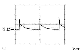
- HINT:
- Gauge set: 5 V/DIV. 5 ms/DIV
- Condition: Ignition switch ON
- Gauge set: 5 V/DIV. 5 ms/DIV
| HEADLIGHT BEAM LEVEL CONTROL ECU |

| Symbols (Terminal No.) |
Wiring Color |
Terminal Description |
Condition |
Specified Condition |
| GND (H17-1) - Body ground |
W-B - Body ground |
Body ground |
Always |
Below 1 V |
| SPDL (H17-5) - GND (H17-1) |
P - W-B |
Skid control ECU (Vehicle speed signal) |
Drive at about 30 km/h (19 mph) |
Pulse generation (*1) |
| SPDR (H17-6) - GND (H17-1) |
O - W-B |
Skid control ECU (Vehicle speed signal) |
Drive at about 30 km/h (19 mph) |
Pulse generation (*1) |
| HDLP (H17-7) - GND (H17-1) |
GR - W-B |
Headlight relay (HEAD signal) |
Light control switch is OFF |
10 to 14 V |
| HDLP (H17-7) - GND (H17-1) |
GR - W-B |
Headlight relay (HEAD signal) |
Light control switch is HEAD |
Below 1 V |
| RHG (H17-9) - GND (H17-1) |
B - W-B |
Headlight beam control actuator RH |
Always |
Below 1 V |
| RH3 (H17-10) - GND (H17-1) |
V - W-B |
Headlight beam control actuator RH |
Ignition switch is OFF |
Below 1 V |
| RH3 (H17-10) - GND (H17-1) |
V - W-B |
Headlight beam control actuator RH |
Engine running, light control switch in HEAD, vehicle stationary and bounced |
Pulse generation (*2) |
| RH1 (H17-11) - GND (H17-1) |
R - W-B |
Headlight beam control actuator RH |
Ignition switch is OFF |
Below 1 V |
| RH1 (H17-11) - GND (H17-1) |
R - W-B |
Headlight beam control actuator RH |
Engine running, light control switch in HEAD, vehicle stationary and bounced |
Pulse generation (*2) |
| RH4 (H17-12) - GND (H17-1) |
W - W-B |
Headlight beam control actuator RH |
Ignition switch is OFF |
Below 1 V |
| RH4 (H17-12) - GND (H17-1) |
W - W-B |
Headlight beam control actuator RH |
Engine running, light control switch in HEAD, vehicle stationary and bounced |
Pulse generation (*2) |
| RH2 (H17-13) - GND (H17-1) |
BR - W-B |
Headlight beam control actuator RH |
Ignition switch is OFF |
Below 1 V |
| RH2 (H17-13) - GND (H17-1) |
BR - W-B |
Headlight beam control actuator RH |
Engine running, light control switch in HEAD, vehicle stationary and bounced |
Pulse generation (*2) |
| IG (H17-14) - GND (H17-1) |
P - W-B |
Ignition (Power source circuit) |
Ignition switch OFF |
Below 1 V |
| IG (H17-14) - GND (H17-1) |
P - W-B |
Ignition (Power source circuit) |
Ignition switch ON |
10 to 14 V |
| SGR (H17-16) - GND (H17-1) |
V - W-B |
Height control sensor signal |
Always |
Below 1 V |
| SHR (H17-18) - SGR (H17-16) |
W - V |
Height control sensor signal |
Ignition switch OFF |
Below 1 V |
| SHR (H17-18) - SGR (H17-16) |
W - V |
Height control sensor signal |
Ignition switch ON, vehicle stationary and bounced |
0.5 to 4.5 V |
| SBR (H17-20) - SGR (H17-16) |
R - V |
Height control sensor signal |
Ignition switch OFF |
Below 1 V |
| SBR (H17-20) - SGR (H17-16) |
R - V |
Height control sensor signal |
Ignition switch ON |
4.5 to 5.5 V |
| WNG (H17-21) - GND (H17-1) |
LG - W-B |
Combination meter (Indicator light circuit) |
Headlight beam warning light goes off |
10 to 14 V |
| WNG (H17-21) - GND (H17-1) |
LG - W-B |
Combination meter (Indicator light circuit) |
Headlight beam warning light comes on |
Below 1 V |
| LHG (H17-22) - GND (H17-1) |
G - W-B |
Headlight beam control actuator LH |
Always |
Below 1 V |
| LH3 (H17-23) - GND (H17-1) |
Y - W-B |
Headlight beam control actuator LH |
Ignition switch OFF |
Below 1 V |
| LH3 (H17-23) - GND (H17-1) |
Y - W-B |
Headlight beam control actuator LH |
Engine running, light control switch in HEAD or DRL system ON, vehicle stationary and bounced |
Pulse generation (*2) |
| LH1 (H17-24) - GND (H17-1) |
O - W-B |
Headlight beam control actuator LH |
Ignition switch OFF |
Below 1 V |
| LH1 (H17-24) - GND (H17-1) |
O - W-B |
Headlight beam control actuator LH |
Engine running, light control switch in HEAD or DRL system ON, vehicle stationary and bounced |
Pulse generation (*2) |
| LH4 (H17-25) - GND (H17-1) |
R - W-B |
Headlight beam control actuator LH |
Ignition switch OFF |
Below 1 V |
| LH4 (H17-25) - GND (H17-1) |
R - W-B |
Headlight beam control actuator LH |
Engine running, light control switch in HEAD or DRL system ON, vehicle stationary and bounced |
Pulse generation (*2) |
| LH2 (H17-26) - GND (H17-1) |
L-B - W-B |
Headlight beam control actuator LH |
Ignition switch OFF |
Below 1 V |
| LH2 (H17-26) - GND (H17-1) |
L-B - W-B |
Headlight beam control actuator LH |
Engine running, light control switch in HEAD or DRL system ON, vehicle stationary and bounced |
Pulse generation (*2) |
*1: Oscilloscope wave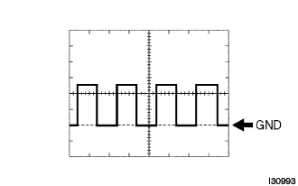
- HINT:
- Terminal: SPDL - GND, SPDR - GND
- Gauge set: 5 V/DIV. 2 ms/DIV
- Condition: Drive at about 30 km/h (19 mph)
- Terminal: SPDL - GND, SPDR - GND
*2: Oscilloscope wave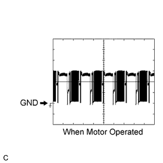
- HINT:
- Terminal: RH1. RH2. RH3. RH4 - GND LH1. LH2. LH3. LH4 - GND
- Gauge set: 5 V/DIV. 10 ms/DIV
- Condition: The DRL system is on with the engine running or the light control switch is in the HEAD position when the vehicle is stationary or being bounced.
- Terminal: RH1. RH2. RH3. RH4 - GND LH1. LH2. LH3. LH4 - GND
| AFS ECU |
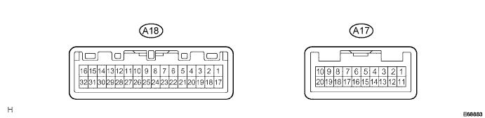
| Symbols (Terminal No.) |
Wiring Color |
Terminal Description |
Condition |
Specified Condition |
| E1 (A17-1) - Body ground |
W-B - Body ground |
Body ground |
Always |
Below 1 V |
| IG (A17-2) - E1 (A17-1) |
P - W-B |
Ignition switch (Power source circuit) |
Ignition switch OFF |
Below 1 V |
| IG (A17-2) - E1 (A17-1) |
P - W-B |
Ignition switch (Power source circuit) |
Ignition switch ON |
10 to 14 V |
| MSW (A17-4) - E1 (A17-1) |
LG - W-B |
AFS OFF switch |
AFS OFF switch is not pressed |
4.5 to 5.5 V |
| MSW (A17-4) - E1 (A17-1) |
LG - W-B |
AFS OFF switch |
AFS OFF switch is pressed |
Below 1 V |
| MPX1 (A17-5) - E1 (A17-1) |
P - W-B |
Multiplex communication signal |
Ignition switch ON |
Signal waveform |
| SS+ (A17-7) - SS- (A17-8) |
LG - Y |
Steering sensor |
Engine idling, slowly turn steering wheel |
Pulse generation |
| SHRL (A17-9) - SGR (A17-20) |
W - V |
Height control sensor rear RH (Vehicle height signal) |
Ignition switch OFF |
Below 1 V |
| SHRL (A17-9) - SGR (A17-20) |
W - V |
Height control sensor rear RH (Vehicle height signal) |
Ignition switch ON, vehicle stationary and bounced |
0.5 to 4.5 V |
| SBR (A17-10) - SGR (A17-20) |
R - V |
Height control sensor rear RH (Vehicle height signal) |
Ignition switch OFF |
Below 1 V |
| SBR (A17-10) - SGR (A17-20) |
R - V |
Height control sensor rear RH (Vehicle height signal) |
Ignition switch ON |
4.5 to 5.5 V |
| E1S (A17-11) - Body ground |
W-B - Body ground |
Body ground |
Always |
Below 1 V |
| IGS (A17-12) - E1 (A17-1) |
P - W-B |
Ignition switch (Signal power source) |
Ignition switch OFF |
Below 1 V |
| IGS (A17-12) - E1 (A17-1) |
P - W-B |
Ignition switch (Signal power source) |
Ignition switch ON |
10 to 14 V |
| SGR (A17-20) - E1 (A17-1) |
V - W-B |
Height control ECU (Vehicle height signal) |
Always |
Below 1 V (*3) |
| SGR (A17-20) - E1 (A17-1) |
V - W-B |
Height control sensor rear RH (Vehicle height signal) |
Always |
Below 1 V (*4) |
| SPDL (A18-6) - E1 (A17-1) |
P - W-B |
Skid control ECU (Vehicle speed signal) |
Drive at about 30 km/h (19 mph) |
Pulse generation (*1) |
| SPDR (A18-7) - E1 (A17-1) |
O - W-B |
Skid control ECU (Vehicle speed signal) |
Drive at about 30 km/h (19 mph) |
Pulse generation (*1) |
| SBLR (A18-9) - SBGR (A18-10) |
L - B |
Headlight swivel ECU RH |
Ignition switch OFF |
Below 1 V |
| SBLR (A18-9) - SBGR (A18-10) |
L - B |
Headlight swivel ECU RH |
Ignition switch ON |
Signal waveform |
| IGSR (A18-12) - E1 (A17-1) |
R - W-B |
Headlight swivel ECU RH |
Ignition switch OFF |
Below 1 V |
| IGSR (A18-12) - E1 (A17-1) |
R - W-B |
Headlight swivel ECU RH |
Ignition switch ON |
10 to 14 V |
| LR1+ (A18-13) - E1 (A17-1) |
B - W-B |
Headlight leveling actuator RH |
Ignition switch OFF |
Below 1 V |
| LR1+ (A18-13) - E1 (A17-1) |
B - W-B |
Headlight leveling actuator RH |
Engine running, light control switch in HEAD, vehicle stationary and bounced |
Pulse generation (*2) |
| LR1- (A18-14) - E1 (A17-1) |
LG - W-B |
Headlight leveling actuator RH |
Ignition switch OFF |
Below 1 V |
| LR1- (A18-14) - E1 (A17-1) |
LG - W-B |
Headlight leveling actuator RH |
Engine running, light control switch in HEAD, vehicle stationary and bounced |
Pulse generation (*2) |
| LR2+ (A18-15) - E1 (A17-1) |
V - W-B |
Headlight leveling actuator RH |
Ignition switch OFF |
Below 1 V |
| LR2+ (A18-15) - E1 (A17-1) |
V - W-B |
Headlight leveling actuator RH |
Engine running, light control switch in HEAD, vehicle stationary and bounced |
Pulse generation (*2) |
| LR2- (A18-16) - E1 (A17-1) |
W - W-B |
Headlight leveling actuator RH |
Ignition switch OFF |
Below 1 V |
| LR2- (A18-16) - E1 (A17-1) |
W - W-B |
Headlight leveling actuator RH |
Engine running, light control switch in HEAD, vehicle stationary and bounced |
Pulse generation (*2) |
| SBLL (A18-25) - SBGL (A18-26) |
P - BR |
Headlight swivel ECU LH |
Ignition switch OFF |
Below 1 V |
| SBLL (A18-25) - SBGL (A18-26) |
P - BR |
Headlight swivel ECU LH |
Ignition switch ON |
Signal waveform |
| IGSL (A18-28) - E1 (A17-1) |
Y - W-B |
Headlight swivel ECU LH |
Ignition switch OFF |
Below 1 V |
| IGSL (A18-28) - E1 (A17-1) |
Y - W-B |
Headlight swivel ECU LH |
Ignition switch ON |
10 to 14 V |
| LL1+ (A18-29) - E1 (A17-1) |
W - W-B |
Headlight leveling actuator LH |
Ignition switch OFF |
Below 1 V |
| LL1+ (A18-29) - E1 (A17-1) |
W - W-B |
Headlight leveling actuator LH |
Engine running, light control switch in HEAD, vehicle stationary and bounced |
Pulse generation (*2) |
| LL1- (A18-30) - E1 (A17-1) |
O - W-B |
Headlight leveling actuator LH |
Ignition switch OFF |
Below 1 V |
| LL1- (A18-30) - E1 (A17-1) |
O - W-B |
Headlight leveling actuator LH |
Engine running, light control switch in HEAD, vehicle stationary and bounced |
Pulse generation (*2) |
| LL2+ (A18-31) - E1 (A17-1) |
GR - W-B |
Headlight leveling actuator LH |
Ignition switch OFF |
Below 1 V |
| LL2+ (A18-31) - E1 (A17-1) |
GR - W-B |
Headlight leveling actuator LH |
Engine running, light control switch in HEAD, vehicle stationary and bounced |
Pulse generation (*2) |
| LL2- (A18-32) - E1 (A17-1) |
B - W-B |
Headlight leveling actuator LH |
Ignition switch OFF |
Below 1 V |
| LL2- (A18-32) - E1 (A17-1) |
B - W-B |
Headlight leveling actuator LH |
Engine running, light control switch in HEAD, vehicle stationary and bounced |
Pulse generation (*2) |
| ESR (A18-11) - P GND (H10-4) |
GR - GR |
Headlight swivel ECU RH ground circuit |
Always |
Below 1 V |
| ESL (A18-11) - P GND (H7-4) |
GR - GR |
Headlight swivel ECU LH ground circuit |
Always |
Below 1 V |
*1: Oscilloscope wave
- HINT:
- Terminal: SPDL - GND, SPDR - GND
- Gauge set: 5 V/DIV. 2 ms/DIV
- Condition: Drive at about 30 km/h (19 mph)
- Terminal: SPDL - GND, SPDR - GND
*2: Oscilloscope wave
- HINT:
- Terminal: LR1+. LR1-. LR2+. LH2- - GND LL1+. LL1-. LL2+. LL2- - GND
- Gauge set: 5 V/DIV. 10 ms/DIV
- Condition: The DRL system is on with the engine running or the light control switch is in the HEAD position when the vehicle is stationary or being bounced.
- Terminal: LR1+. LR1-. LR2+. LH2- - GND LL1+. LL1-. LL2+. LL2- - GND