Door Courtesy Switch Circuit
Circuit diagnosis
DESCRIPTION
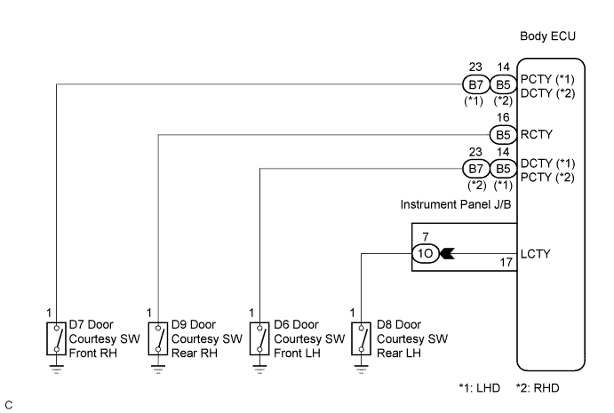
The body ECU detects the condition of the door courtesy switch assembly.WIRING DIAGRAM

INSPECTION PROCEDURE
| 1. READ VALUE OF INTELLIGENT TESTER |

Connect the intelligent tester to the DLC3.
Turn the ignition switch to the ON position and press the intelligent tester main switch ON.
Select the items below in the DATA LIST, and read the displays on the intelligent tester.
BODY NO.1: Item
Measurement Item/
Display (Range)
Normal Condition
Diagnostic Note
D Door Courtesy SW
Driver's door courtesy SW signal/ON or OFF OK
ON: Driver's door is open
OFF: Driver's door is closed
-
Rear Door Courtesy SW
Rear door courtesy SW signal/ON or OFF
ON: Either right or left rear door is open
OFF: Both the right and left doors are closed
-
|
|
||||

| OK | ||
 |
||
| ||
| 2. INSPECT COURTESY LIGHT SWITCH |
Inspect the front door courtesy switch (Click here).
Inspect the rear door courtesy switch (Click here).
|
|
||||

| OK | |
 |
| 3. CHECK HARNESS AND CONNECTOR (COURTESY LIGHT SWITCH - INSTRUMENT PANEL J/B ASSEMBLY) |
Disconnect the 1O, B5 and B7 connectors from the instrument panel junction block assembly.
Measure the resistance according to the value(s) in the table below.
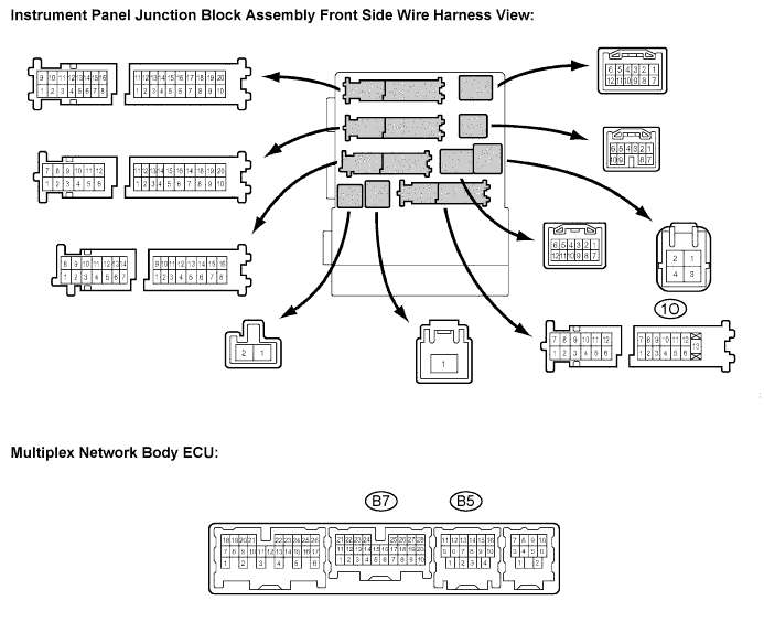
- Resistance:
Tester connection
Condition
Specified condition
B5-14 - Body ground (*1)
B7-23 - Body ground (*2)
Front LH door is OPEN
Front LH door is CLOSE
Below 1 Ω
10 kΩ or higher
B7-23 - Body ground (*1)
B5-14 - Body ground (*2)
Front RH door is OPEN
Front RH door is CLOSE
Below 1 Ω
10 kΩ or higher
1O-7 - Body ground
Rear LH door is OPEN
Rear LH door is CLOSE
Below 1 Ω
10 kΩ or higher
B5-16 - Body ground
Rear RH door is OPEN
Rear RH door is CLOSE
Below 1 Ω
10 kΩ or higher
|
|
||||
| OK | ||
|
||
| ||