B2215 Back door does not operate
Diagnostic trouble codes
DESCRIPTION
This DTC is output when the position switch in the back door has a malfunction. This position switch detects if the back door is in the open/close position and sends a position signal to the power back door ECU.| DTC No. |
DTC Detection Condition |
Trouble Area |
| B2215 |
Back door does not operate |
|
- NOTICE:
- The power back door ECU records the back door positions in the memory. In the case where any of the batteries, fuses, power back door ECU and power back door drive unit are removed and then reinstalled, the power back door ECU loses the memory of the door positions. In such a case, resetting the power back door system is necessary. Refer to the resetting operation specified in page Click here.
WIRING DIAGRAM
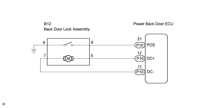

INSPECTION PROCEDURE
| 1. CHECK WIRE HARNESS (BACK DOOR LOCK ASSEMBLY - POWER BACK DOOR ECU) |

Disconnect the back door lock assembly connectors.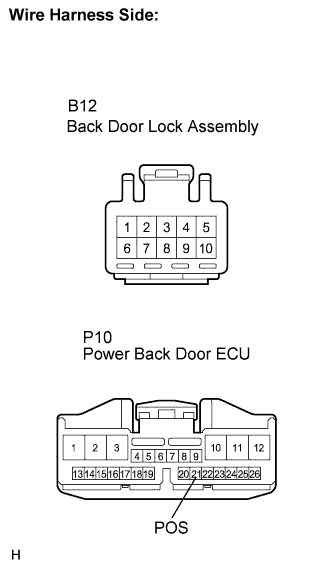
Disconnect the power back door ECU connectors.
Measure the resistance according to the value(s) in the table below.
- Standard resistance:
Tester Connection
Condition
Specified Condition
B12-8 - P10-21 (POS)
Always
Below 1 Ω
B12-9 - Body ground
Always
Below 1 Ω
|
|
||||

| OK | |
 |
| 2. INSPECT BACK DOOR LOCK ASSEMBLY (DOOR LOCK MOTOR) |
Check operation of the door lock.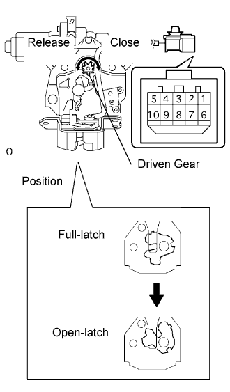
Using a screwdriver, push the latch in order to put the back door lock in the locked condition (full-latch position).
Apply battery voltage and check operation of the latch.
- OK:
Measurement Condition
Specified Condition
Battery positive (+) → Terminal 7
Battery negative (-) → Terminal 5
Latch turns to open-latch position
Check motor operation when battery voltage is applied to the terminals.
- OK:
Measurement Condition
Specified Condition
Battery positive (+) → Terminal 5
Battery negative (-) → Terminal 7
Close operation (Full-latch)
Battery positive (+) → Terminal 7
Battery negative (-) → Terminal 5
Release operation (Open-latch)
|
|
||||
| OK | |
|
| 3. INSPECT BACK DOOR LOCK ASSEMBLY (SWITCH) |
Measure the position switch resistance.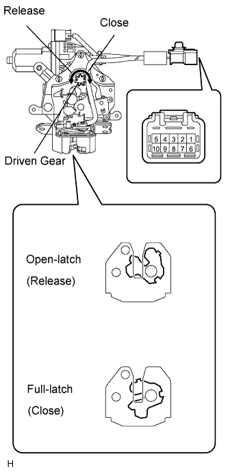
Connect the battery positive (+) lead to connector terminal 7 and the negative (-) lead to connector terminal 5.
Measure the resistance according to the value(s) in the table below.
- Standard resistance:
Tester Connection
Driven Gear Position
Specified Condition
8 - 9
Release
Below 1 Ω
Connect the battery positive (+) lead to connector terminal 5 and the negative (-) lead to connector terminal 7.
Measure the resistance according to the value(s) in the table below.
- Standard resistance:
Tester Connection
Driven Gear Position
Specified Condition
8 - 9
Close
10 kΩ or higher
|
|
||||
| OK | ||
 |
||
| ||