Power Source Circuit
Circuit diagnosis
DESCRIPTION
This is the power source circuit for the outer mirror control ECU.WIRING DIAGRAM
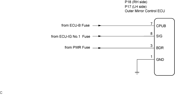

INSPECTION PROCEDURE
| 1. INSPECT OUTER MIRROR CONTROL ECU (POWER SOURCE) |

Disconnect the R17 (R18) connector.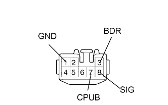
Measure the voltage and resistance according to the value(s) in the table below.
- Outer mirror control ECU LH:
- Standard voltage:
Tester Connection
Condition
Specified Condition
R17-3 (BDR) - Body ground
Always
10 to 14 V
R17-7 (CPUB) - Body ground
Always
10 to 14 V
R17-8 (SIG) - Body ground
Ignition switch ON
10 to 14 V
- Standard resistance:
Tester Connection
Condition
Specified Condition
R17-1 (GND) - Body ground
Always
Below 1 Ω
- Outer mirror control ECU RH:
- Standard voltage:
Tester Connection
Condition
Specified Condition
R18-3 (BDR) - Body ground
Always
10 to 14 V
R18-7 (CPUB) - Body ground
Always
10 to 14 V
R18-8 (SIG) - Body ground
Ignition switch ON
10 to 14 V
- Standard resistance:
Tester Connection
Condition
Specified Condition
R18-1 (GND) - Body ground
Always
Below 1 Ω
|
|
||||

| OK | ||
 |
||
| ||