TERMINALS OF ECU
System information
| CHECK TRANSPONDER KEY AMPLIFIER |
Disconnect the T7 amplifier connector and measure the resistance between the terminal of the wire harness side connector and body ground.


If the result is not as specified, there may be a malfunction on the wire harness side.Symbols (Terminal No.)
Wiring Color
Terminal Description
Condition
Specified Condition
GND (T7-7) - Body ground
W - Body ground
Ground
Always
Below 1 Ω
Reconnect the T8 amplifier connector and measure the resistance and voltage of each terminal of the connector.
If the result is not as specified, the amplifier may have a malfunction.Symbols (Terminal No.)
Wiring Color
Terminal Description
Condition
Specified Condition
VC5 (T7-1) - GND (T7-7)
P - W
Power source
No key is in ignition key cylinder
Below 1 V
Key is in ignition key cylinder
4.6 to 5.4 V
CODE (T7-4) - GND (T7-7)
LG - W
Demodulated signal of key code date
No key is in ignition key cylinder
Below 1 V
Key is in ignition key cylinder
Waveform 1
TEXT (T7-5) - GND (T7-7)
BR - W
Key code output signal
No key is in ignition key cylinder
Below 1 V
Key is in ignition key cylinder
Waveform 2
GND (T7-7) - Body ground
W - Body ground
Ground
Always
Below 1 Ω
Inspect using an oscilloscope.
Waveform 1 (Reference):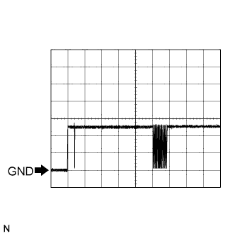
Terminal
CODE - GND
Tool Setting
2 V/DIV., 20 ms/DIV.
Condition
Key is in ignition key cylinder
Waveform 2 (Reference):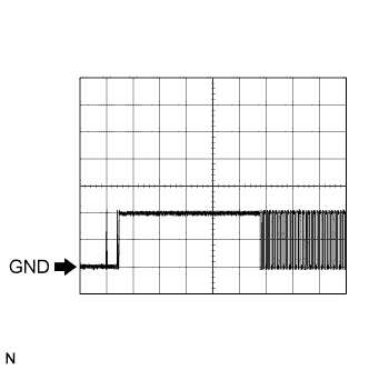
Terminal
TXCT - GND
Tool Setting
2 V/DIV., 10 ms/DIV.
Condition
Key is in ignition key cylinder
| CHECK TRANSPONDER KEY ECU ASSEMBLY |
Disconnect the T8 ECU connector and measure the resistance and voltage between each terminal of the wire harness side connector.

If the result is not as specified, there may be a malfunction on the wire harness side.Symbols (Terminal No.)
Wiring Color
Terminal Description
Condition
Specified Condition
CPUB (T8-1) - GND (T8-14)
V - W-B
Battery
Always
10 to 14 V
IG2 (T8-2) - GND (T8-14)
V - W
Ignition switch
Ignition switch off
Below 1 V
Ignition switch on
10 to 14 V
KSW (T8-3) - GND (T8-14)
B - W
Unlock warning switch
No key is in ignition key cylinder
10 kΩ or higher
Key is in ignition key cylinder
Below 1 Ω
MPX1 (T8-4) - Body ground
O - Body ground
MPX line
Always
10 kΩ or higher
MPX2 (T8-5) - Body ground
R (LHD) - Body ground
MPX line
Always
10 kΩ or higher
MPX2 (T8-5) - Body ground
Y (RHD) - Body ground
MPX line
Always
10 kΩ or higher
Reconnect the T8 ECU connector and measure the voltage of each terminal of the connector.
If the result is not as specified, the ECU may have a malfunction.Symbols (Terminal No.)
Wiring Color
Terminal Description
Condition
Specified Condition
AGND (T8-13) - Body ground
W - Body ground
Ground
Always
Below 1 Ω
KSW (T8-3) - GND (T8-14)
B - W
Unlock warning switch
No key is in ignition key cylinder
10 to 14 V
Key is in ignition key cylinder
Below 1 V
VC5 (T8-9) - AGND (T8-13)
P - W
Power source
Ignition switch off
Below 1 V
Ignition switch on
4.6 to 5.4 V
TXCT (T8-12) - AGND (T8-13)
BR - W
Transponder key amplifier communication signal
No key is in ignition key cylinder
Below 1 V
Key is in ignition key cylinder
Waveform 1
CODE (T8-10) - AGND (T8-13)
LG - W
Transponder key amplifier ground
No key is in ignition key cylinder
Below 1 V
Key is in ignition key cylinder
Waveform 2
EFIO (T8-6) - GND (T8-14)
GR - W
Hybrid vehicle control ECU output signal
Ignition switch off
Below 1 V
Ignition switch on
Waveform 3
EFII (T8-7) - GND (T8-14)
L - W
Hybrid vehicle control ECU input signal
Ignition switch off
Below 1 V
Ignition switch on
Waveform 4
Inspect using an oscilloscope.
Waveform 1 (Reference):
Terminal
TXCT - AGND
Tool Setting
2 V/DIV., 10 ms/DIV.
Condition
Key is in ignition key cylinder
Waveform 2 (Reference):
Terminal
CODE - AGND
Tool Setting
2 V/DIV., 20 ms/DIV.
Condition
Key is in ignition key cylinder
Waveform 3 (Reference):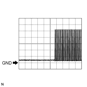
Terminal
EFIO - GND
Tool Setting
2 V/DIV., 1 s/DIV.
Condition
Ignition switch on
Waveform 4 (Reference):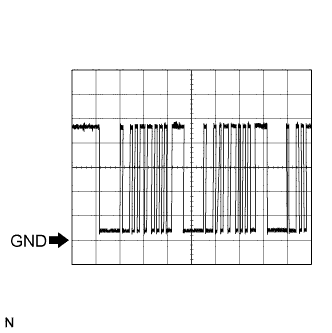
Terminal
EFII - GND
Tool Setting
2 V/DIV., 200 ms/DIV.
Condition
Ignition switch on
| CHECK HYBRID VEHICLE CONTROL ECU |
Disconnect the H32 hybrid vehicle control ECU connector and measure the resistance between the terminal of the wire harness side connector and body ground.
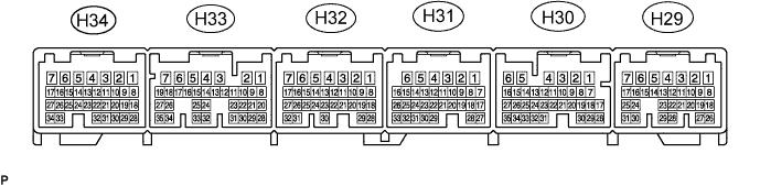
If the result is not as specified, there may be a malfunction on the wire harness side.Symbols (Terminal No.)
Wiring Color
Terminal Description
Condition
Specified Condition
E1 (H32-5) - Body ground
BR - Body ground
Ground
Always
Below 1 Ω
Reconnect the H32 hybrid vehicle control ECU. Measure the voltage between each terminal of the connector according to the value(s) in the table below.
If the result is not as specified, there may be a malfunction on the wire harness side.Symbols (Terminal No.)
Wiring Color
Terminal Description
Condition
Specified Condition
IMI (H29-22) - E1 (H32-5)
GR - BR
Transponder key ECU input signal
Ignition switch off
Below 1 V
Ignition switch on
Waveform 1
IMO (H29-28) - E1 (H32-5)
L- BR
Transponder key ECU output signal
Ignition switch off
Below 1 V
Ignition switch on
Waveform 2
Inspect using an oscilloscope.
Waveform 1 (Reference):
Terminal
IMI - E1
Tool Setting
2 V/DIV., 1 s/DIV.
Condition
Ignition switch on
Waveform 2 (Reference):
Terminal
IMO - E1
Tool Setting
2 V/DIV., 200 ms/DIV.
Condition
Ignition switch on