ECU Power Source Circuit
Circuit diagnosis
DESCRIPTION
This circuit provides power to the transponder key ECU.WIRING DIAGRAM
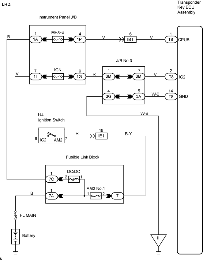

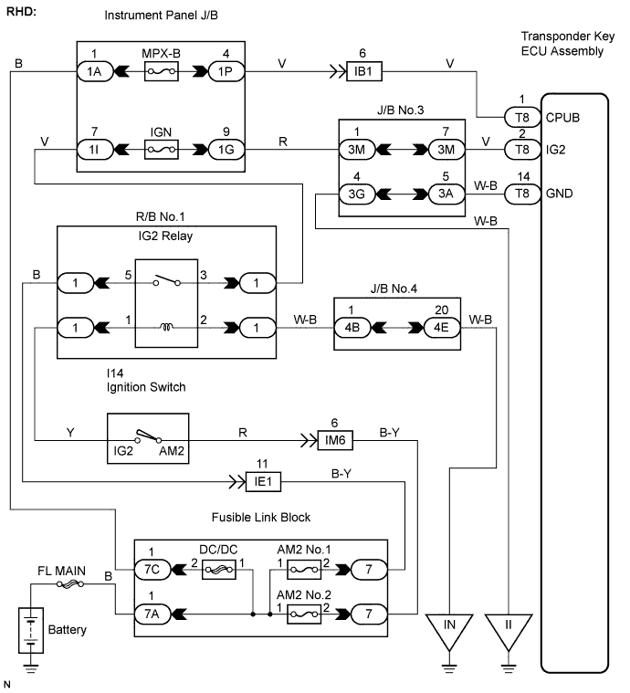
INSPECTION PROCEDURE
| 1. CHECK FUSES (MPX-B, IGN, AM2 No.1) |

Remove the MPX-B, IGN fuses from the instrument panel J/B.
Remove the AM2 No.1 (LHD, RHD) and AM2 No.2 (RHD) fuses from the fusible link block.
Measure the resistance of the fuse(s).
- Resistance:
- Below 1 Ω
|
|
||||

| OK | |
 |
| 2. CHECK HARNESS AND CONNECTOR (TRANSPONDER KEY ECU ASSEMBLY - BATTERY) |
Disconnect T8 ECU connector.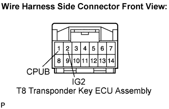
Measure the voltage according to the value(s) in the table below.
- Voltage:
Tester Connection
Condition
Specified Condition
T8-2 (IG2) - Body ground
Ignition switch off
Below 1 V
T8-2 (IG2) - Body ground
Ignition switch on
10 to 14 V
T8-1 (CPUB) - Body ground
Always
0 to 14 V
|
|
||||
| OK | |
|
| 3. CHECK HARNESS AND CONNECTOR (TRANSPONDER KEY ECU ASSEMBLY - BODY GROUND) |
Measure the resistance according to the value(s) in the table below.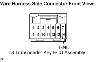
- Resistance:
Tester Connection
Condition
Specified Condition
T8-14 (GND) - Body ground
Always
Below 1 Ω
|
|
||||
| OK | ||
 |
||
| ||