B2784 Antenna coil open/short
Diagnostic trouble codes
DESCRIPTION
The transponder key coil is built into the transponder key amplifier and receives a key code signal from the transponder chip in the key. This signal is amplified by the amplifier, and output to the transponder key ECU.| DTC No. |
DTC Detection Condition |
Trouble Area |
| B2784 |
Antenna coil open/short |
|
WIRING DIAGRAM
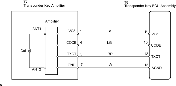

INSPECTION PROCEDURE
| 1. READ VALUE OF INTELLIGENT TESTER |

Connect the intelligent tester to the DLC3.
Turn the ignition switch on and turn the intelligent tester main switch on.
Select Antenna Coil Status in the DATA LIST and read the value displayed on the intelligent tester.
Transponder key ECU: Item
Measurement Item/Display (Range)
Normal Condition
Diagnostic Note
Antenna Coil Status
Antenna coil condition /NORMAL or FAIL
NORMAL: Antenna coil is normal.
FAIL: Antenna coil is malfunctioning.
-
- OK:
- NORMAL (Antenna coil is normal) appears on the screen.
|
|
||||

| NG | |
 |
| 2. CHECK HARNESS AND CONNECTOR (TRANSPONDER KEY ECU ASSEMBLY - TRANSPONDER KEY AMPLIFIER) |
Disconnect the T8 ECU and T7 switch connectors.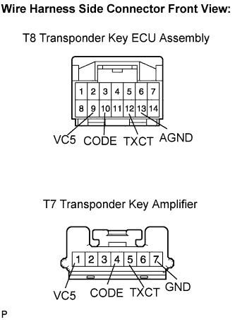
Measure the resistance according to the value(s) in the table below.
- Resistance:
Tester Connection
Specified Condition
T8-9 (VC5) - T7-1 (VC5)
Below 1 Ω
T8-10 (CODE) - T7-4 (CODE)
T8-12 (TXCT) - T7-5 (TXCT)
T8-13 (AGND) - T7-7 (GND)
T8-9 (VC5) or T7-1(VC5) - Body ground
10 kΩ or higher
T8-10 (CODE) or T7-4 (CODE) - Body ground
T8-12 (TXCT) or T7-5 (TXCT) - Body ground
T8-13 (AGND) or T7-7 (GND) - Body ground
|
|
||||
| OK | |
|
| 3. INSPECT TRANSPONDER KEY ECU ASSEMBLY |
Reconnect the T8 ECU and T7 amplifier connectors.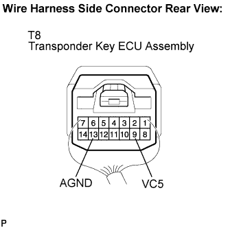
Measure the voltage according to the value(s) in the table below.
- Voltage:
Tester Connection
Condition
Specified Condition
T8-9 (VC5) - Body ground
No key is in ignition key cylinder
Below 1 V
Key is in ignition key cylinder
4.6 to 5.4 V
Measure the resistance according to the value(s) in the table below.
- Resistance:
Tester Connection
Condition
Specified Condition
T9-13 (AGND) - Body ground
Always
Below 1 Ω
|
|
||||
| OK | |
|
| 4. CHECK OPERATION OF TRANSPONDER KEY AMPLIFIER |
After replacing the transponder key amplifier with a normally functioning transponder key amplifier, check that the hybrid control system starts.
- OK:
- Hybrid control system starts.
|
|
||||
| OK | ||
 |
||
| ||