Open in CAN Main Bus Line
Circuit diagnosis
DESCRIPTION
There may be an open circuit in the CAN main bus line and/or the DLC3 sub bus line when the resistance between terminals 6 (CANH) and 14 (CANL) of the DLC3 is 69 Ω or higher.| Symptom |
Suspected Area |
| Resistance between terminals 6 (CANH) and 14 (CANL) of the DLC3 is 69 Ω or higher. |
|
WIRING DIAGRAM
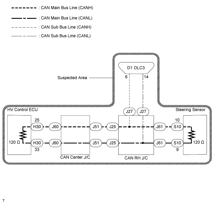

INSPECTION PROCEDURE
| 1. CHECK DLC3 |

Turn the ignition switch off.
Measure the resistance according to the value(s) in the table below.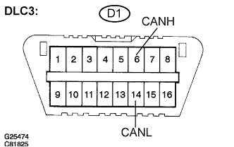
- Result:
Tester Connection
Condition
Specified Value
Proceed To
D1-6 (CANH) - D1-14 (CANL)
Disconnect the negative auxiliary battery cable
108 to 132 Ω
A
D1-6 (CANH) - D1-14 (CANL)
Disconnect the negative auxiliary battery cable
132 Ω or higher
B
- NOTICE:
- When the measured value is 132 Ω or higher and the CAN communication system diagnostic code is output, there may be a fault besides an open in the DLC3 sub bus line. For that reason, troubleshooting should be performed again from "HOW TO PROCEED WITH TROUBLESHOOTING" (Click here) after repairing the trouble area.
|
|
||||

| A | |
 |
| 2. CHECK CAN MAIN BUS LINE FOR DISCONNECTION (BUS CHECK) |
Perform 'Communication Bus Check' using the intelligent tester (Click here).
- Result:
Specified Condition
Proceed to
"STEERING SENSOR" only is not displayed
A
"HV CONTROL" only is not displayed
B
Others
C
|
|
||||
|
|
||||

| A | |
|
| 3. CHECK CAN MAIN BUS LINE FOR DISCONNECTION (STEERING SENSOR - CAN RH J/C) |
Disconnect the steering sensor connector (S10).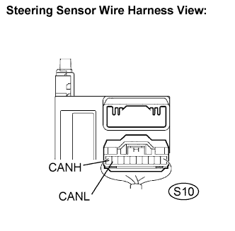
Measure the resistance according to the value(s) in the table below.
- Standard Resistance:
Tester Connection
Condition
Specified Value
S10-10 (CANH) - S10-9 (CANL)
Disconnect the negative auxiliary battery cable
108 to 132 Ω
|
|
||||
| OK | ||
 |
||
| ||
| 4. CHECK CAN MAIN BUS LINE FOR DISCONNECTION (HV CONTROL ECU - CAN CENTER J/C) |
Disconnect the HV control ECU connector (H30).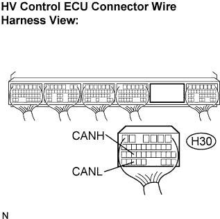
Measure the resistance according to the value(s) in the table below.
- Standard Resistance:
Tester Connection
Condition
Specified Value
H30-25 (CANH) - H30-33 (CANL)
Disconnect the negative auxiliary battery cable
108 to 132 Ω
|
|
||||
| OK | ||
|
||
| ||
| 5. CHECK CAN MAIN BUS LINE FOR DISCONNECTION |
Disconnect the steering sensor connector (S10).
Measure the resistance according to the value(s) in the table below.
- Standard Resistance:
Tester Connection
Condition
Specified Value
S10-10 (CANH) - S10-9 (CANL)
Disconnect the negative auxiliary battery cable
108 to 132 Ω
|
|
||||
| NG | |
|
| 6. CONNECT CONNECTOR |
Reconnect the steering sensor connector (S10).
| NEXT | |
|
| 7. CHECK CAN MAIN BUS LINE FOR DISCONNECTION |
Disconnect the steering sensor main bus line connector (J61) from the CAN RH J/C B side (w/o earth terminal).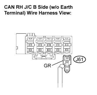
- NOTICE:
- Before disconnecting the connector, make a note of where it is connected.
- Reconnect the connector to its original position.
- Before disconnecting the connector, make a note of where it is connected.
Measure the resistance according to the value(s) in the table below.
- Standard Resistance:
Tester Connection
Condition
Specified Value
J61-1 (CANH) - J61-2 (CANL)
Disconnect the negative auxiliary battery cable
108 to 132 Ω
|
|
||||
| OK | |
|
| 8. CONNECT CONNECTOR |
Reconnect the steering sensor main bus line connector (J61) to the CAN RH J/C B side (w/o earth terminal).
| NEXT | |
|
| 9. CHECK CAN MAIN BUS LINE FOR DISCONNECTION |
Disconnect the CAN main bus line connector (J25) from the CAN RH J/C B side (w/o earth terminal).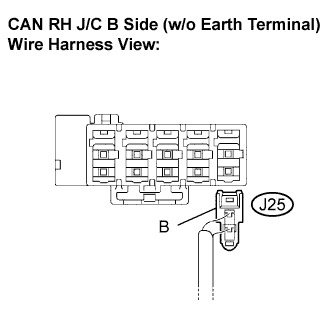
Measure the resistance according to the value(s) in the table below.
- Standard Resistance:
Tester Connection
Condition
Specified Value
J25-1 (CANH) - J25-2 (CANL)
Disconnect the negative auxiliary battery cable
108 to 132 Ω
|
|
||||
| NG | |
|
| 10. CONNECT CONNECTOR |
Reconnect the CAN main bus line connector (J25) to the CAN RH J/C B side (w/o earth terminal).
| NEXT | |
|
| 11. CHECK CAN MAIN BUS LINE FOR DISCONNECTION |
Disconnect the CAN main bus line connector (J51) from the CAN center J/C A side (w/ earth terminal).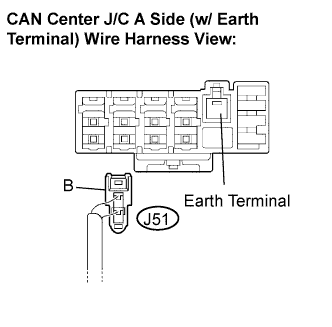
- NOTICE:
- Before disconnecting the connector, make a note of where it is connected.
- Reconnect the connector to its original position.
- Before disconnecting the connector, make a note of where it is connected.
Measure the resistance according to the value(s) in the table below.
- Standard Resistance:
Tester Connection
Condition
Specified Value
J51-1 (CANH) - J51-2 (CANL)
Disconnect the negative auxiliary battery cable
108 to 132 Ω
|
|
||||
| OK | |
|
| 12. CONNECT CONNECTOR |
Reconnect the CAN main bus line connector (J51) to the CAN center J/C A side (w/ earth terminal).
| NEXT | |
|
| 13. CHECK CAN MAIN BUS LINE FOR DISCONNECTION |
Disconnect the HV control ECU main bus line connector (J60) from the CAN center J/C A side (w/ earth terminal).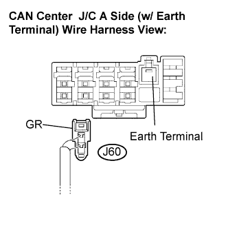
- NOTICE:
- Before disconnecting the connector, make a note of where it is connected.
- Reconnect the connector to its original position.
- Before disconnecting the connector, make a note of where it is connected.
Measure the resistance according to the value(s) in the table below.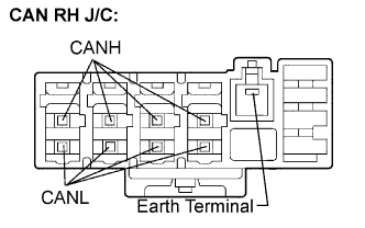
- Standard Resistance:
Tester Connection
Condition
Specified Value
(CANH) - (CANL)
Disconnect the negative auxiliary battery cable
108 to 132 Ω
|
|
||||
| OK | |
|
| 14. CONNECT CONNECTOR |
Reconnect the HV control ECU main bus line connector (J60) to the CAN center J/C A side (w/ earth terminal).
| NEXT | |
|
| 15. CHECK CAN MAIN BUS LINE FOR DISCONNECTION |
Disconnect the HV control ECU connector (H30).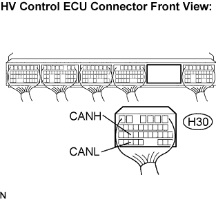
Measure the resistance according to the value(s) in the table below.
- Standard Resistance:
Tester Connection
Condition
Specified Value
H30-25 (CANH) - H30-33(CANL)
Disconnect the negative auxiliary battery cable
108 to 132 Ω
|
|
||||
| NG | ||
|
||
| ||