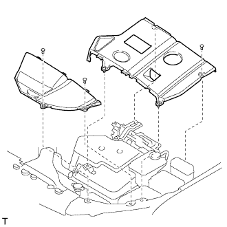
INSTALLATION
Removal / installation
| 1. INSPECT TIMING BELT |

- NOTICE:
- Do not bend, twist or turn the timing belt inside out.
- Do not allow the timing belt to come into contact with oil, water or steam.
- Do not utilize timing belt tension when installing or removing the mounting bolt of the camshaft timing pulley.
- Do not bend, twist or turn the timing belt inside out.
If there is premature parting: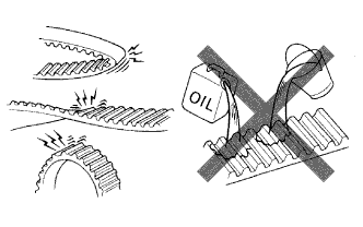

- Check for proper installation.
- Check the timing cover gasket for damage and proper installation.
- Check for proper installation.
If the belt teeth are cracked or damaged, check if either camshaft is locked.
If there is noticeable wear or cracks on the belt face, check if there are nicks on the side of the idler pulley lock and water pump.
If there is wear or damage to only one side of the belt, check the belt guide and the alignment of each pulley.
If there is noticeable wear on the belt teeth:
- Check the timing cover for damage.
- Check that the gasket has been installed correctly.
- Check for foreign object on the pulley teeth.
- Check the timing cover for damage.
| 2. INSTALL TIMING BELT |
Remove any oil or water on the pulleys, and keep them clean.
- NOTICE:
- If there is a trace of water and/or oil on the timing belt, repair the leakage and install a new timing belt.
- Wipe only the pulleys; do not use any cleaning agent.
- If there is a trace of water and/or oil on the timing belt, repair the leakage and install a new timing belt.
Inspect the idler pulleys.
Check that the idler pulley turns smoothly.
Visually check the seal portion of the idler pulley for oil leakage.
Inspect the water pump.
Turn the pulley, and check that the water pump bearing moves smoothly and does not make any noise.
Visually check the drain hole for coolant leakage.
Temporarily install the crankshaft pulley bolt and washer to the crankshaft.
Turn the crankshaft counterclockwise by approximately 60°.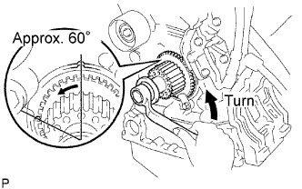
- NOTICE:
- To prevent contacting the piston head and the valve head, set the crankshaft pulley at 60° BTDC/compression position.
Using SST, turn the timing pulleys, and align the timing marks of the timing pulleys with the No.3 timing belt cover.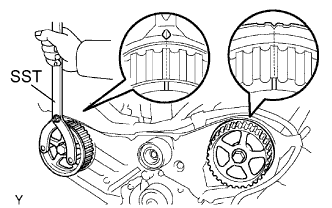
- SST
- 09960-10010
(09962-01000, 09963-01000)
- NOTICE:
- Be sure to hold the SST with the timing marks aligned to prevent the left bank pulley from deviating to the right.
Turn the crankshaft, and align the timing mark of the crankshaft timing pulley with the oil pump body.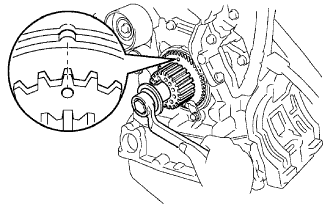
Face the front mark on the timing belt forward.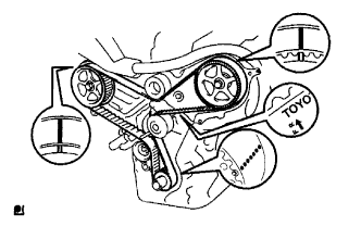
Align the installation mark on the timing belt with the timing mark of the crankshaft timing pulley.
Align the installation marks on the timing belt with the timing marks of the camshaft timing pulleys.
Install the timing belt in the following order.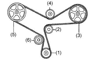
1st
Crankshaft timing pulley
2nd
Water pump pulley
3rd
LH camshaft timing pulley
4th
No.2 idler pulley
5th
RH camshaft timing pulley
6th
No.1 idler pulley
- NOTICE:
- Be sure to hold the SST with the timing marks aligned to prevent the left bank pulley from deviating to the right.
| 3. INSTALL CHAIN TENSIONER ASSEMBLY NO.1 |
Set the timing belt tensioner upright on the press.
Slowly press in the push rod.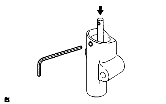
- NOTICE:
- Do not apply pressure more than 9.8 kN (1,000 kgf, 2,205 lbf) to the rod.
Align the holes of the push rod and housing, and pass a 1.5 mm hexagon wrench through the holes to keep the setting position of the push rod.
Release the press.
Temporarily install the tensioner with the 2 bolts. Alternately tighten the 2 bolts.
- Torque:
- 27 N*m{ 280 kgf*cm , 20 ft.*lbf }
- NOTICE:
- Be sure to tighten the bolts equally. Installing the tensioner at an angle may cause improper operation.
Remove the 1.5 mm hexagon wrench from the tensioner.
Turn the crankshaft 2 revolutions slowly and align the timing mark of the crankshaft timing pulley with the oil pump body.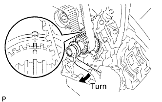
- NOTICE:
- Always turn the crankshaft clockwise.
Check the timing marks of the RH and LH timing pulleys are aligned with the timing marks of the No.3 timing belt cover as shown in the illustration.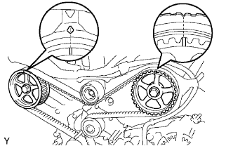
If the marks do not align, remove the timing belt and reinstall it.
Remove the crankshaft pulley bolt.
| 4. INSTALL TIMING BELT GUIDE NO.2 |
Install the timing belt guide with the cup side facing toward the engine front.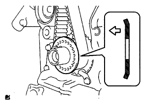
| 5. INSTALL ENGINE MOUNTING BRACKET RH |
Install the engine mounting bracket RH with the 2 bolts and 2 nuts.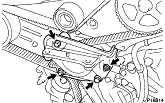
- Torque:
- 28 N*m{ 286 kgf*cm , 21 ft.*lbf }
| 6. INSTALL TIMING BELT NO.2 COVER |
Visually check for cracks and breaks on the gasket of the timing belt cover.
If a trace of water is found in the visual check, replace the timing belt cover.
Install the timing belt cover with the 5 bolts.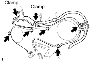
- Torque:
- 8.5 N*m{ 87 kgf*cm , 75 in.*lbf }
Connect the 2 clamps.
| 7. INSTALL TIMING BELT NO.1 COVER |
Visually check for cracks and breaks on the gasket of the timing belt cover.
If a trace of water is found in the visual check, replace the timing belt cover.
Install the timing belt cover.
- Torque:
- 8.5 N*m{ 87 kgf*cm , 75 in.*lbf }
Install the engine wire protector cover to the timing belt No.3 cover.
| 8. INSTALL CRANKSHAFT PULLEY |
Align the keyway of the pulley with the key located on the crankshaft and slide the pulley into place.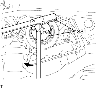
Using SST, install the pulley bolt.
- SST
- 09213-54015
(91651-60855)
09330-00021
- Torque:
- 220 N*m{ 2,250 kgf*cm , 162 ft.*lbf }
| 9. INSTALL ENGINE MOUNTING STAY NO.2 RH |
Install the engine mounting stay No.2 and the engine mounting bracket No.2 with the bolt.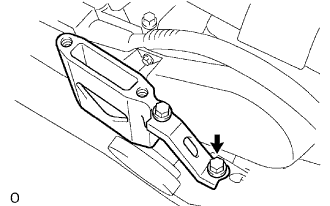
- Torque:
- 64 N*m{ 653 kgf*cm , 47 ft.*lbf }
| 10. INSTALL ENGINE MOVING CONTROL ROD |
Temporarily tighten bolts B and C.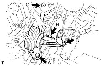
First tighten bolt A, bolt B, then bolt C in this order.
- Torque:
- 64 N*m{ 653 kgf*cm , 47 ft.*lbf }
Tighten bolt D.
- Torque:
- 23 N*m{ 235 kgf*cm , 17 ft.*lbf }
| 11. INSTALL AIR CLEANER BRACKET |
Install the 2 bolts and air cleaner bracket.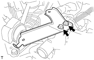
- Torque:
- 27 N*m{ 275 kgf*cm , 20 ft.*lbf }
| 12. INSTALL RESERVOIR BRACKET |
Install the 2 bolts, nut and reservoir bracket.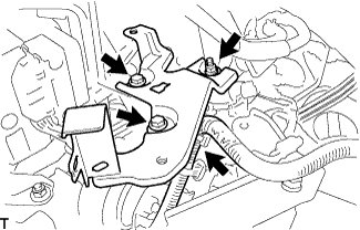
- Torque:
- 9.0 N*m{ 92 kgf*cm , 80 in.*lbf }
Connect the clamp.
| 13. INSTALL BRAKE MASTER CYLINDER RESERVOIR SUB-ASSEMBLY |
Install the 2 bolts and brake master cylinder reservoir to the bracket.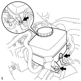
- Torque:
- 9.0 N*m{ 92 kgf*cm , 80 in.*lbf }
Connect the connector.
| 14. INSTALL AIR CLEANER CASE W/ RESONATOR |
Separate the ventilation hose No.2.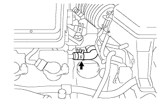
Disconnect the MAF meter connector.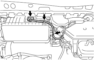
Disconnect the 2 wire harness clamps from the air cleaner.
Remove the 5 bolts from the air cleaner case w/ resonator.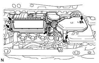
Remove the hose clamp, and separate the air cleaner hose No.1.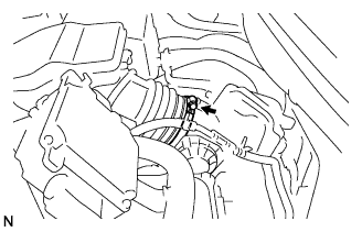
Remove the air cleaner case w/ resonator.
| 15. INSTALL AIR CLEANER CAP W/ INLET |
Install the air cleaner filter element to the air cleaner case.
Install the 2 bolts, 4 clamps and air cleaner cap w/ inlet.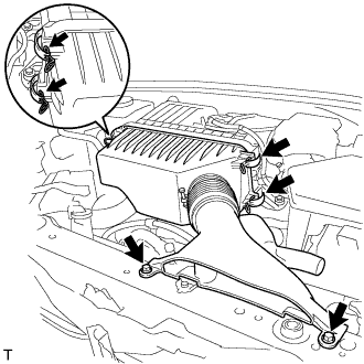
- Torque:
- 7.0 N*m{ 71 kgf*cm , 62 in.*lbf }
| 16. INSTALL COOL AIR INTAKE DUCT SEAL |
Install the 4 clips and cool air intake duct seal.
| 17. INSTALL BATTERY CARRIER SUB-ASSEMBLY |
Install the 5 bolts and battery carrier.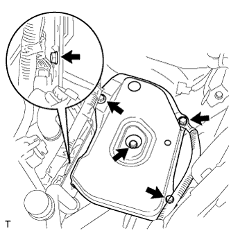
- Torque:
- 19 N*m{ 194 kgf*cm , 14 ft.*lbf }
| 18. INSTALL BATTERY |
Install the battery clamp and battery.
- Torque:
- 5.4 N*m{ 55 kgf*cm , 48 in.*lbf }
| 19. INSTALL COWL TOP PANEL SUB-ASSEMBLY OUTER |
Remove the 4 shock absorber nuts.
Install the 4 bolts, 2 nuts and cowl top panel sub-assembly.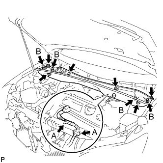
- Torque:
- 5.0 N*m{ 51 kgf*cm , 44 in.*lbf }
Install the 4 shock absorber nuts (B).
- Torque:
- 80 N*m{ 815 kgf*cm , 59 ft.*lbf }
Install the wire harness clamp and grommet (A).
| 20. INSTALL WINDSHIELD WIPER MOTOR AND LINK ASSEMBLY |
Install the windshield wiper motor and link assembly with the 5 bolts.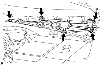
- Torque:
- 7.0 N*m{ 71 kgf*cm , 62 in.*lbf }
Connect the connector.
| 21. INSTALL COWL TOP VENTILATOR LOUVER SUB-ASSEMBLY |
| 22. INSTALL FRONT WIPER ARM AND BLADE ASSEMBLY LH |
Operate the front wiper, and stop the front wiper motor at the automatic stop position.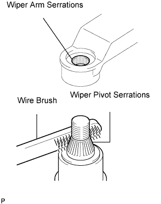
Clean the wiper arm serrations.
Clean the wiper pivot serrations with a wire brush (when reinstalling).
Install the front wiper arm and blade assembly LH with the nut at the position as shown in the illustration.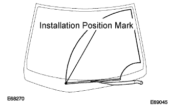
- Torque:
- 24 N*m{ 245 kgf*cm , 18 ft.*lbf }
- HINT:
- Hold the arm hinge by hand to fasten the nut.
| 23. INSTALL FRONT WIPER ARM AND BLADE ASSEMBLY RH |
Clean the wiper arm serrations.
Clean the wiper pivot serrations with a wire brush (when reinstalling).
Install the front wiper arm and blade assembly RH with the 2 nuts at the position as shown in the illustration.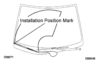
- Torque:
- 24 N*m{ 245 kgf*cm , 18 ft.*lbf }
- HINT:
- Hold the arm hinge by hand to fasten the nut.
Operate the front wipers while spraying water or washer fluid on the windshield.
Make sure that the wipers function properly and there is no interference with the vehicle body.
| 24. INSTALL FRONT FENDER APRON SEAL RH |
Install the 2 bolts, clip and fender apron seal RH.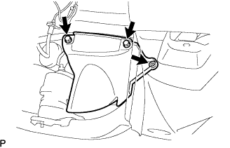
| 25. INSTALL FRONT FENDER SPLASH SHIELD SUB-ASSEMBLY RH |
Install the fender splash shield with the screw.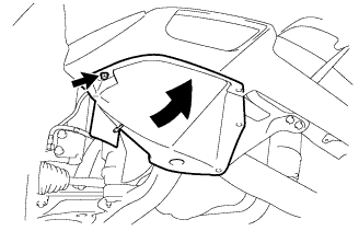
| 26. INSTALL ENGINE UNDER COVER NO.1 |
Install the 6 bolts, 2 screws, 2 clips and engine under cover.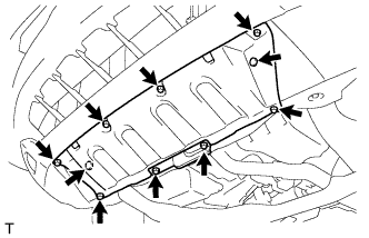
| 27. INSTALL FRONT WHEEL RH |
| 28. INSPECT IGNITION TIMING |
Set the vehicle to inspection mode (Click here).
Warm up the engine.
When using the intelligent tester:
Connect the intelligent tester (with CAN VIM) to the DLC3.
Enter DATA LIST MODE on the intelligent tester.
- Ignition timing:
- 8 to 12° BTDC
- NOTICE:
- Turn all the electrical systems off.
- Inspect the engine idle speed with the cooling fan off.
- Turn all the electrical systems off.
- HINT:
- Refer to the intelligent tester operator's manual if you need help to select DATA LIST.
Check that the ignition timing advances immediately when the engine speed is increased.
When not using the intelligent tester: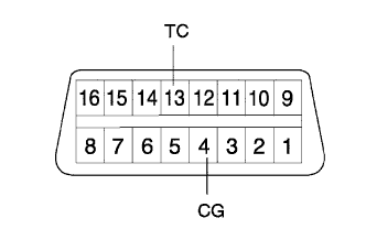
Using SST, connect terminals 13 (TC) and 4 (CG) of the DLC3.
- SST
- 09843-18040
- NOTICE:
- Make sure of the terminal numbers before connecting them. Connection with a wrong terminal can damage the engine.
- Turn off all electrical systems before connecting the terminals.
- Perform this inspection after the cooling fan motor is turned off.
- Make sure of the terminal numbers before connecting them. Connection with a wrong terminal can damage the engine.
Pull out the red-colored wire harness as shown in the illustration.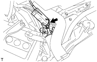
Connect the tester terminal of the timing light to the engine.
- NOTICE:
- Use a timing light which detects the first signal.
Inspect ignition timing at idle.
- Ignition timing:
- 8 to 12° BTDC
- NOTICE:
- When checking the ignition timing, the transmission is in neutral.
- HINT:
- Run the engine at 1,000 to 1,300 rpm for 5 seconds, check that the engine rpm returns to idle speed.
Disconnect terminals 13 (TC) and 4 (CG) of the DLC3.
Inspect ignition timing at idle.
- Ignition timing:
- 7 to 24° BTDC
Confirm that the ignition timing advances when the engine rpm is increased.
Remove the timing light.
| 29. PERFORM INITIALIZATION |
Some system need initialization when reconnecting the battery cable. (Click here)
| 30. INSTALL ENGINE ROOM COVER SIDE |
Install the 5 clips and engine room cover side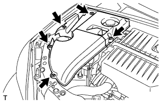
| 31. INSTALL ENGINE ROOM SIDE LH COVER |
Fit the clips and install the engine room side LH cover.